Architecture and Building Technologist
Was challenged in one of our projects to create a conceptual model mirroring the key elements that we envision to use for our proposal. As my assigned client was a musician, I had initially considered using the two music theories of Pentatonic Scale and the Octave (with intent on a repetition at 8ths).
This triggered an exploration on Harmonic Series, the fundamental basis for how chords are made, and the very reason why we hear notes and think they sound good together. This is also naturally occuring in nature. (Fundamentals – overtones – harmonics)
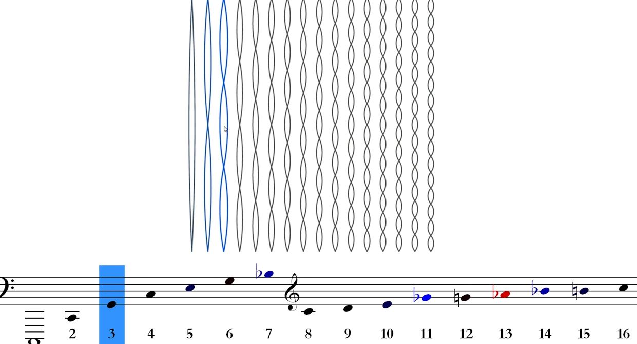
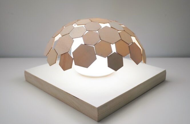
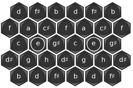
While exploring the concept further, I had refined the approach to focus on perfects 5ths which is the musical interval corresponding to a pair of pitches with a frequency ratio of 3:2. This led me to the Harmonic Table (Or tonal array, developed in the 18th century) which proved to be an interesting launching point for deriving the key element in the design. A hexagon tile.

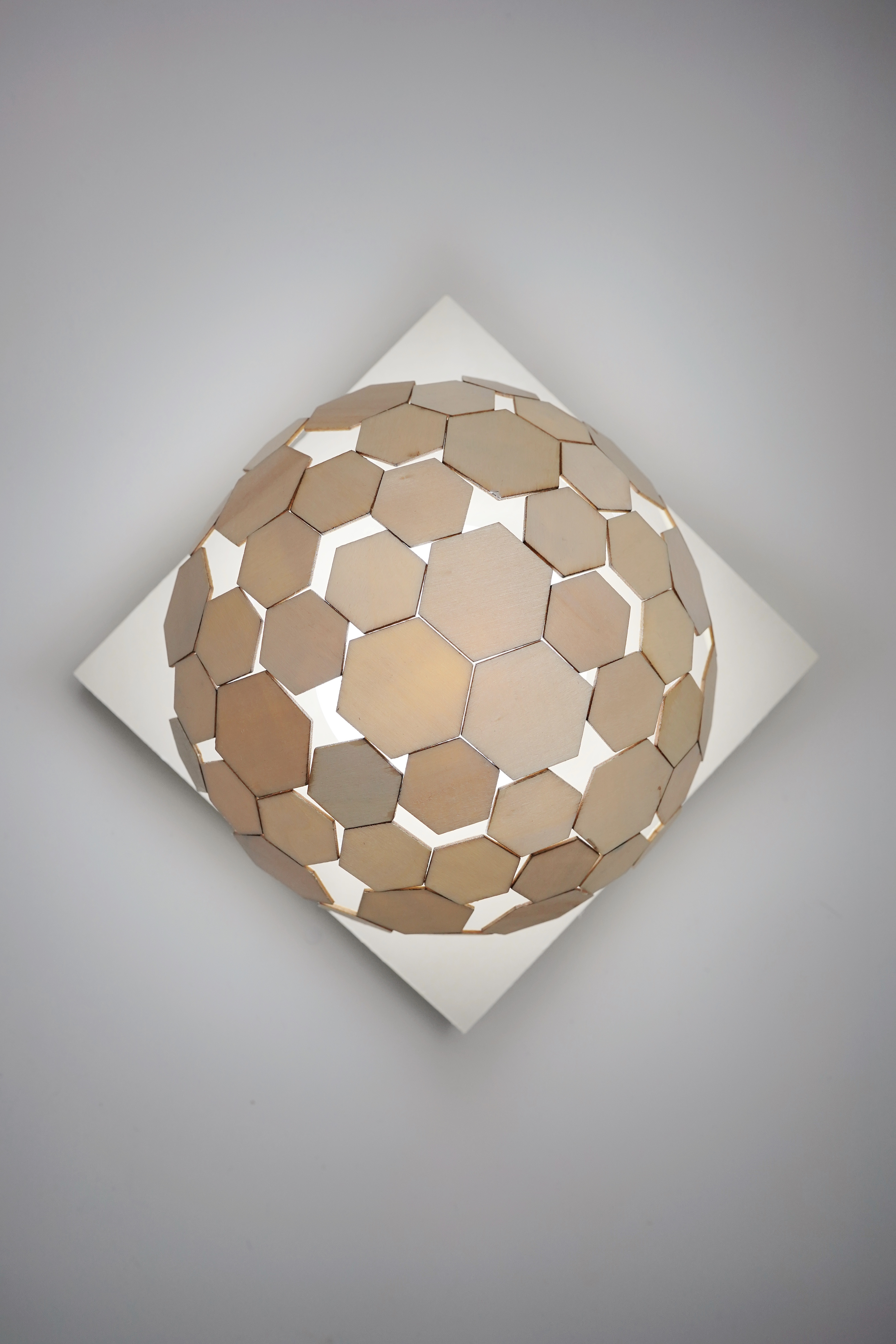
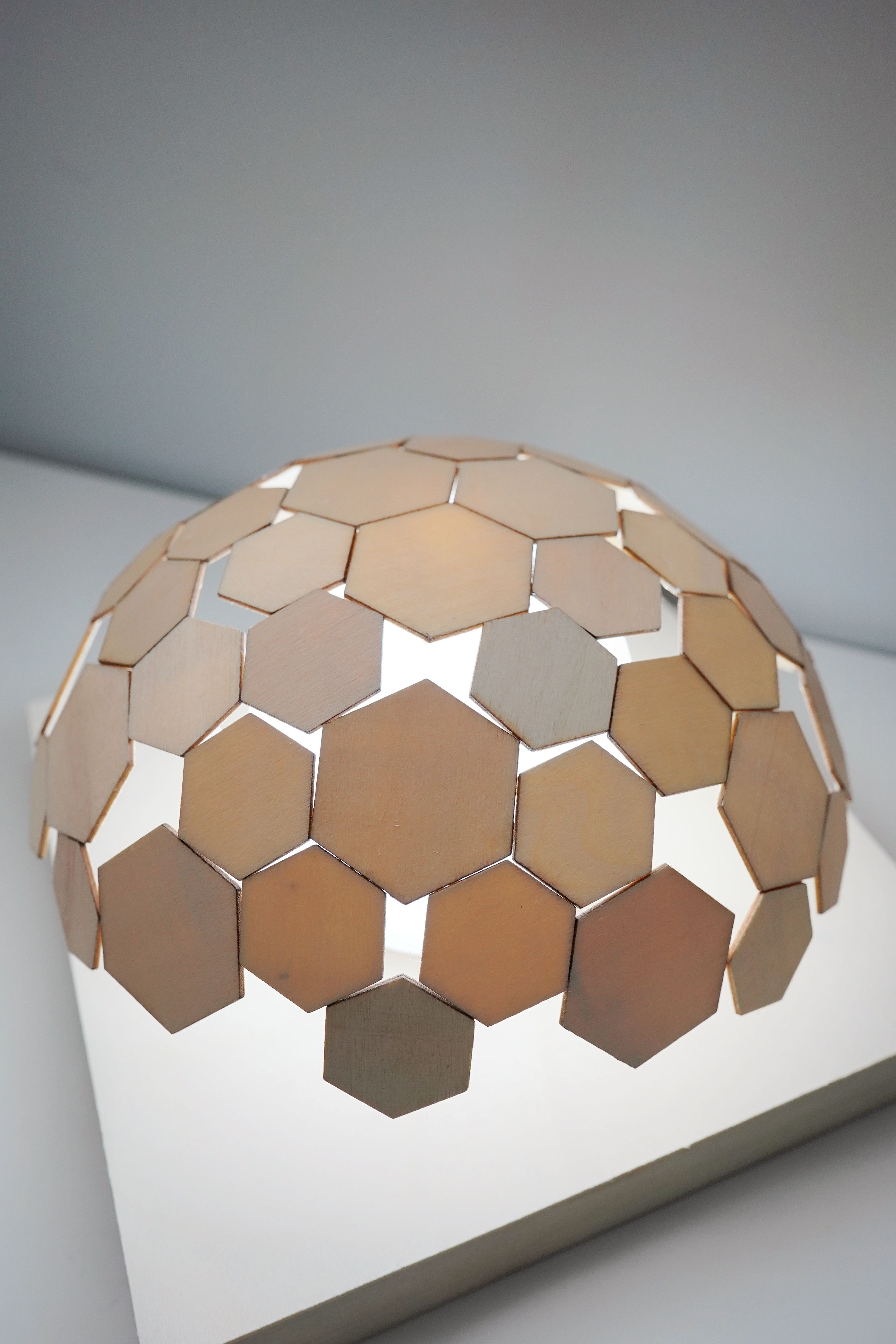
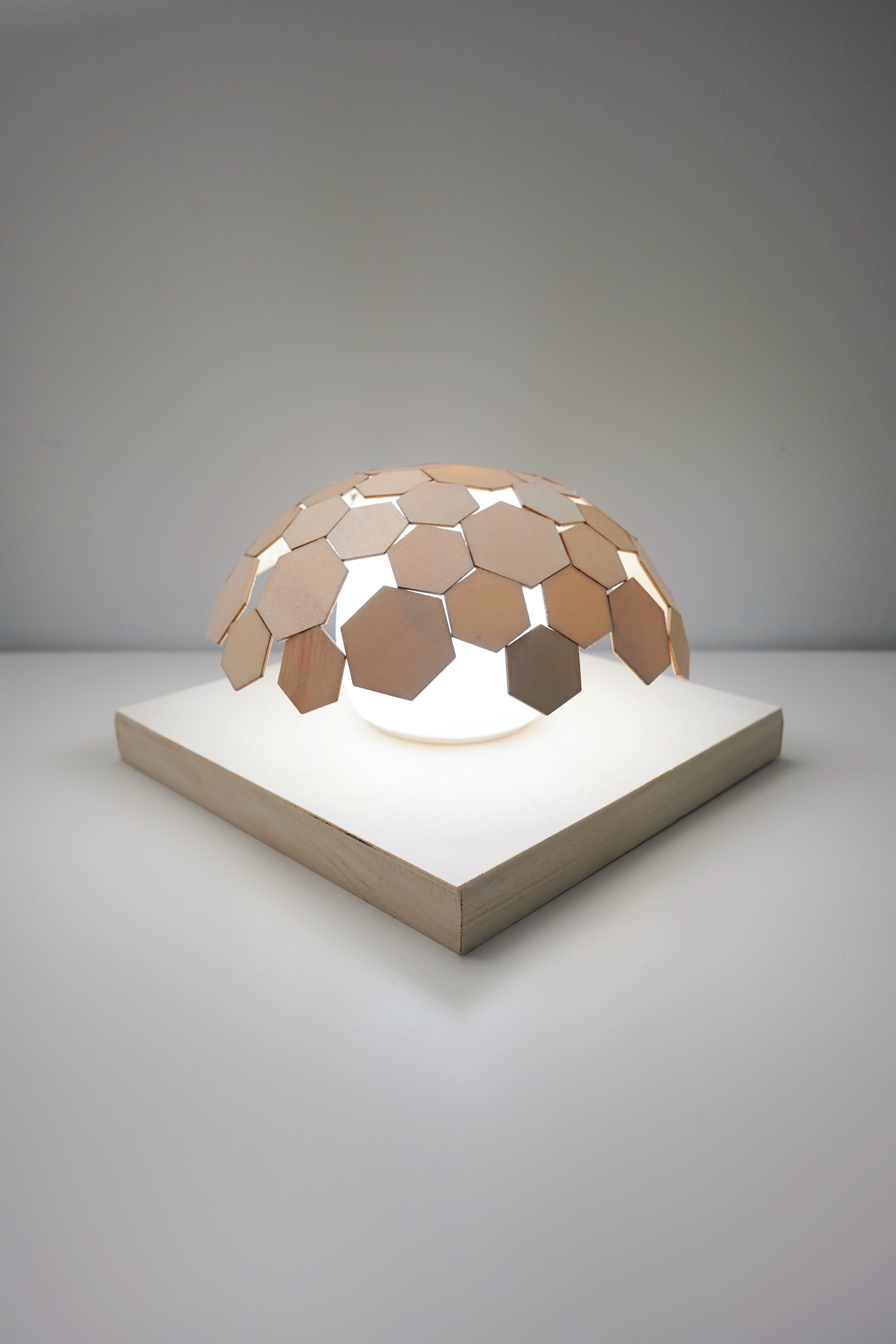
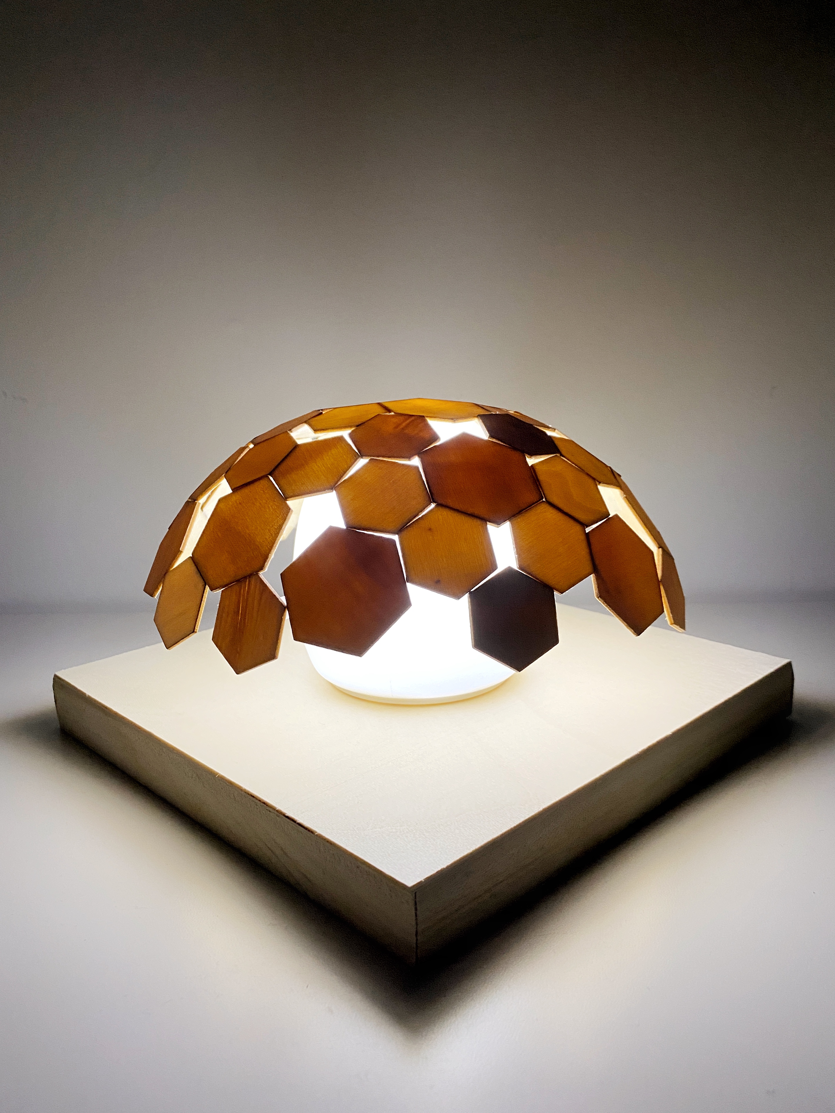
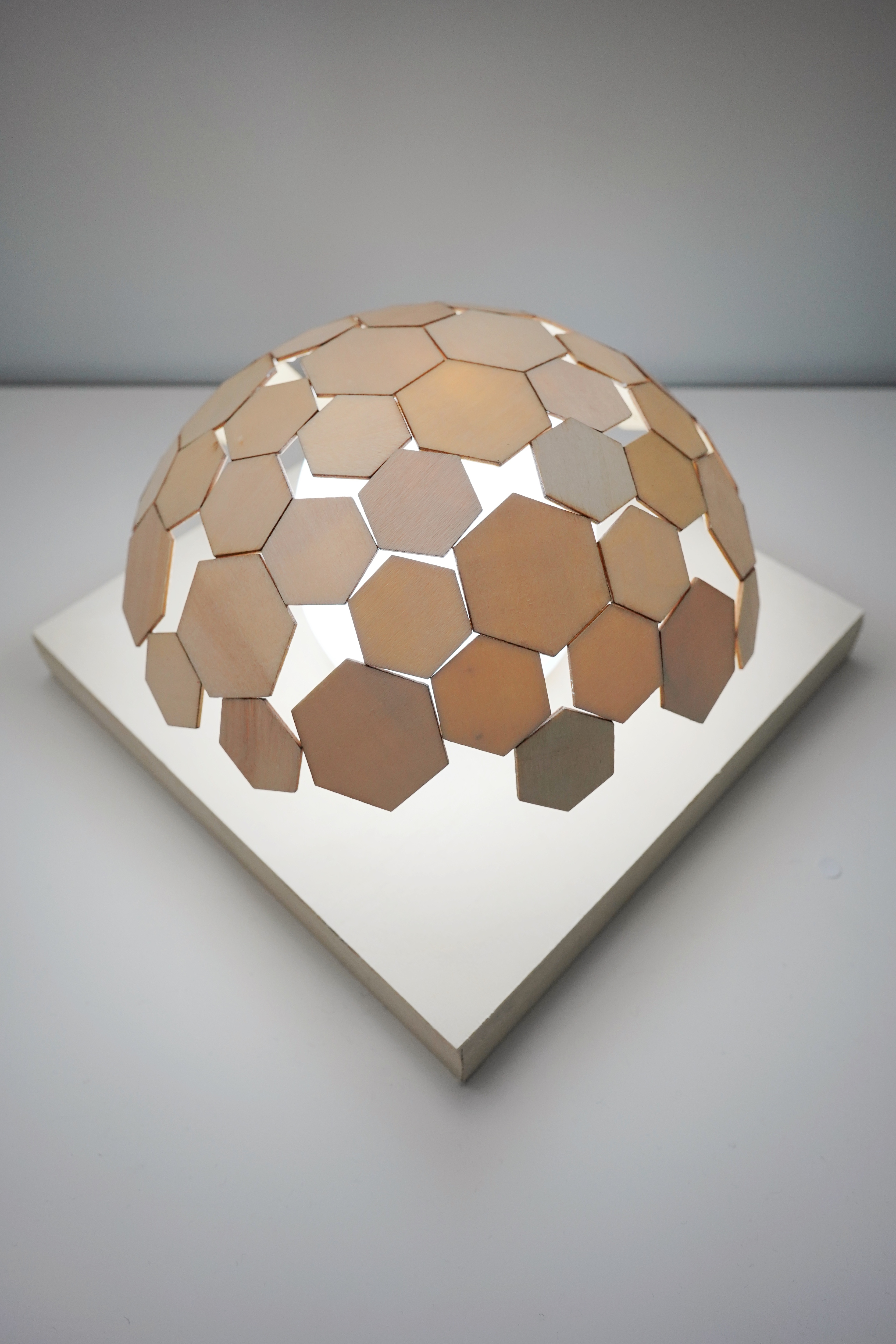
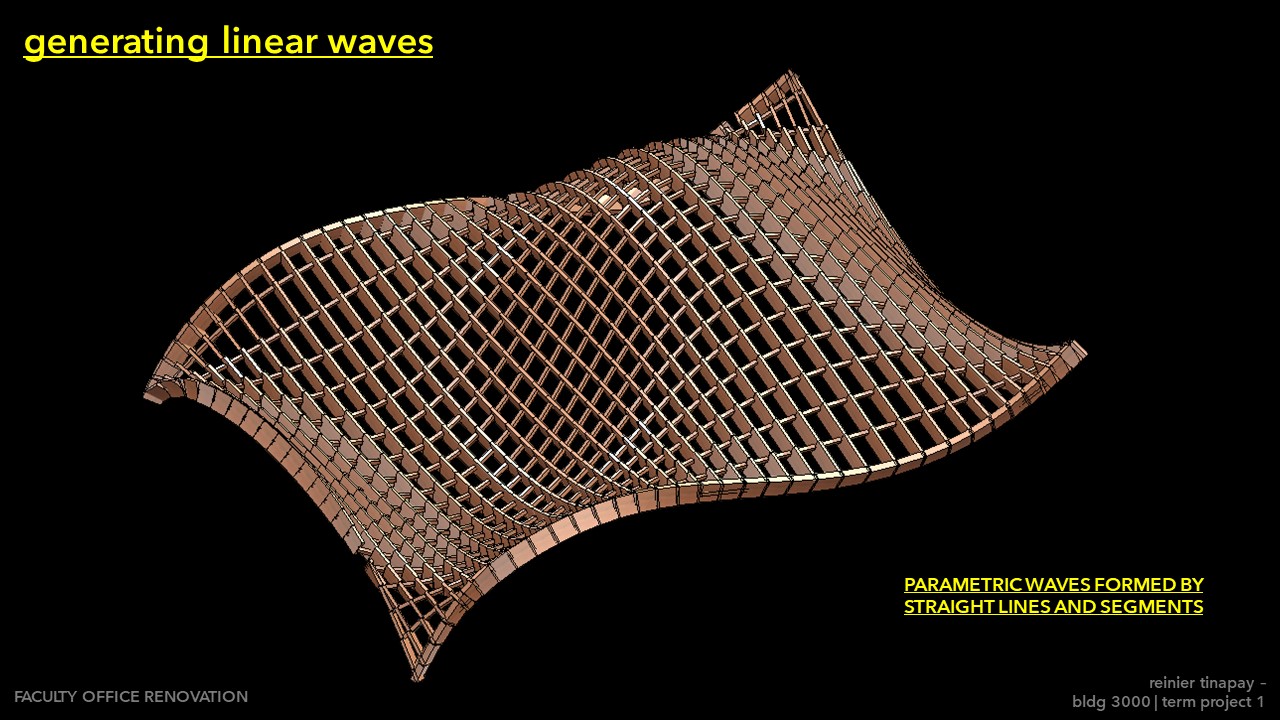
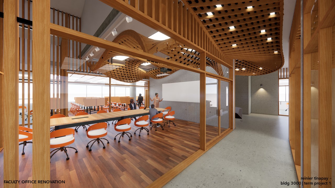
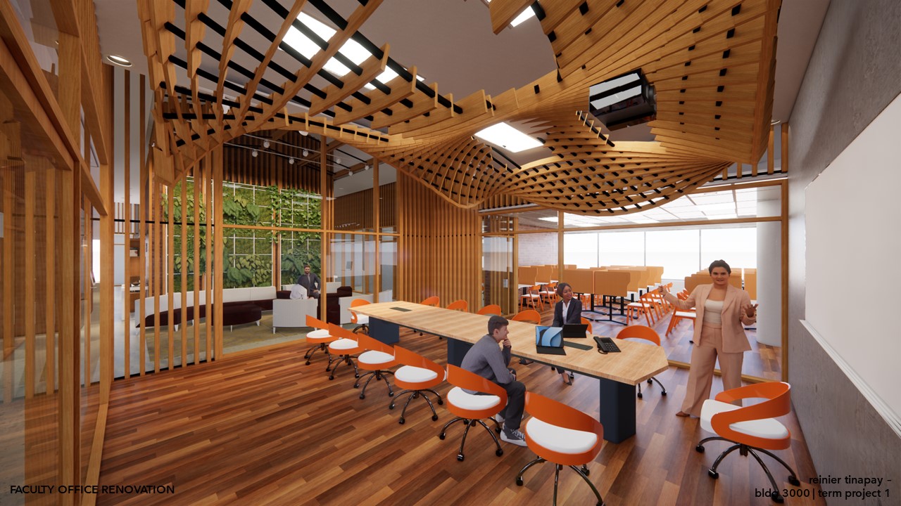
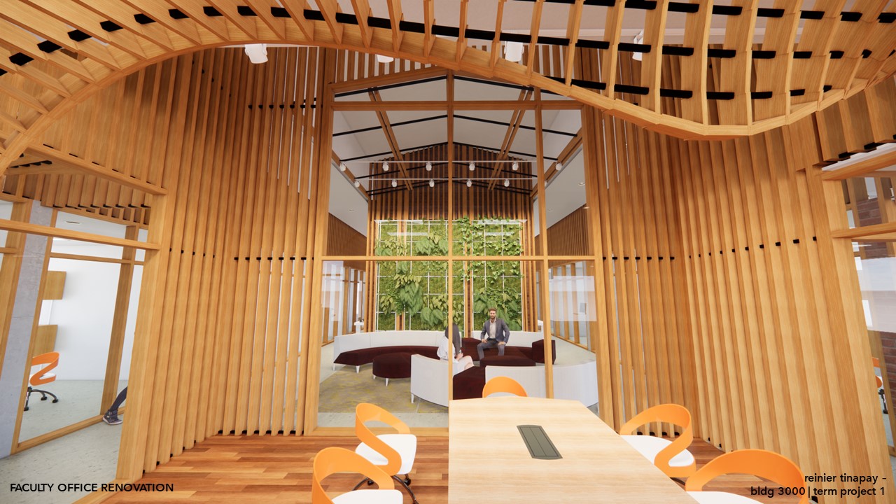
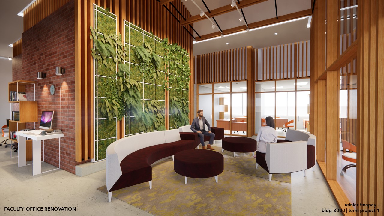
Developing further from this concept, we used hexagon tiles to generate an array of form that spreads across to create a curved form. Flat-to-curve. It is noted that the hexagon appears in nature in several forms, most notable as bee hive and in snow flakes.
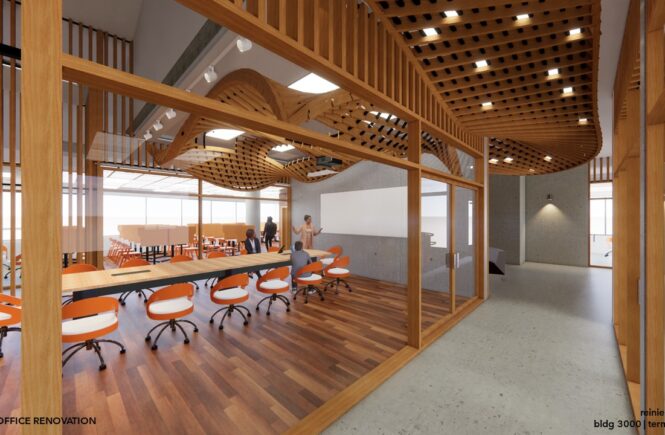
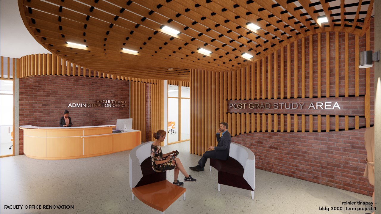
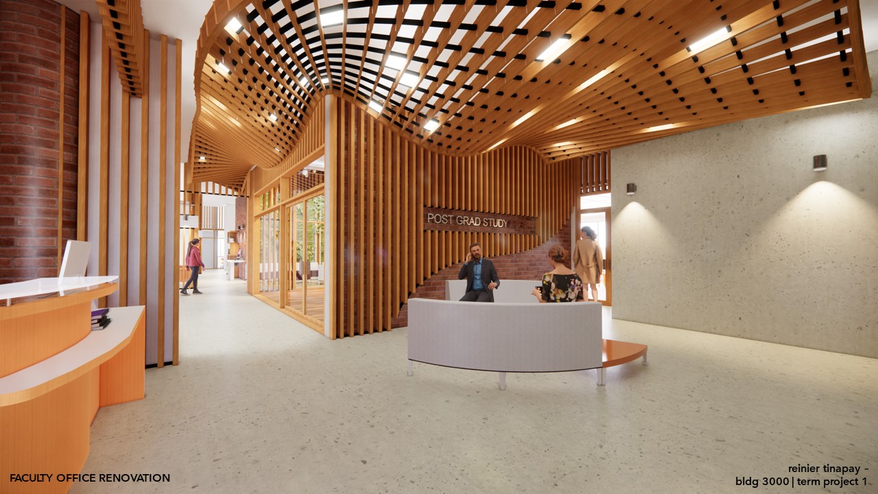
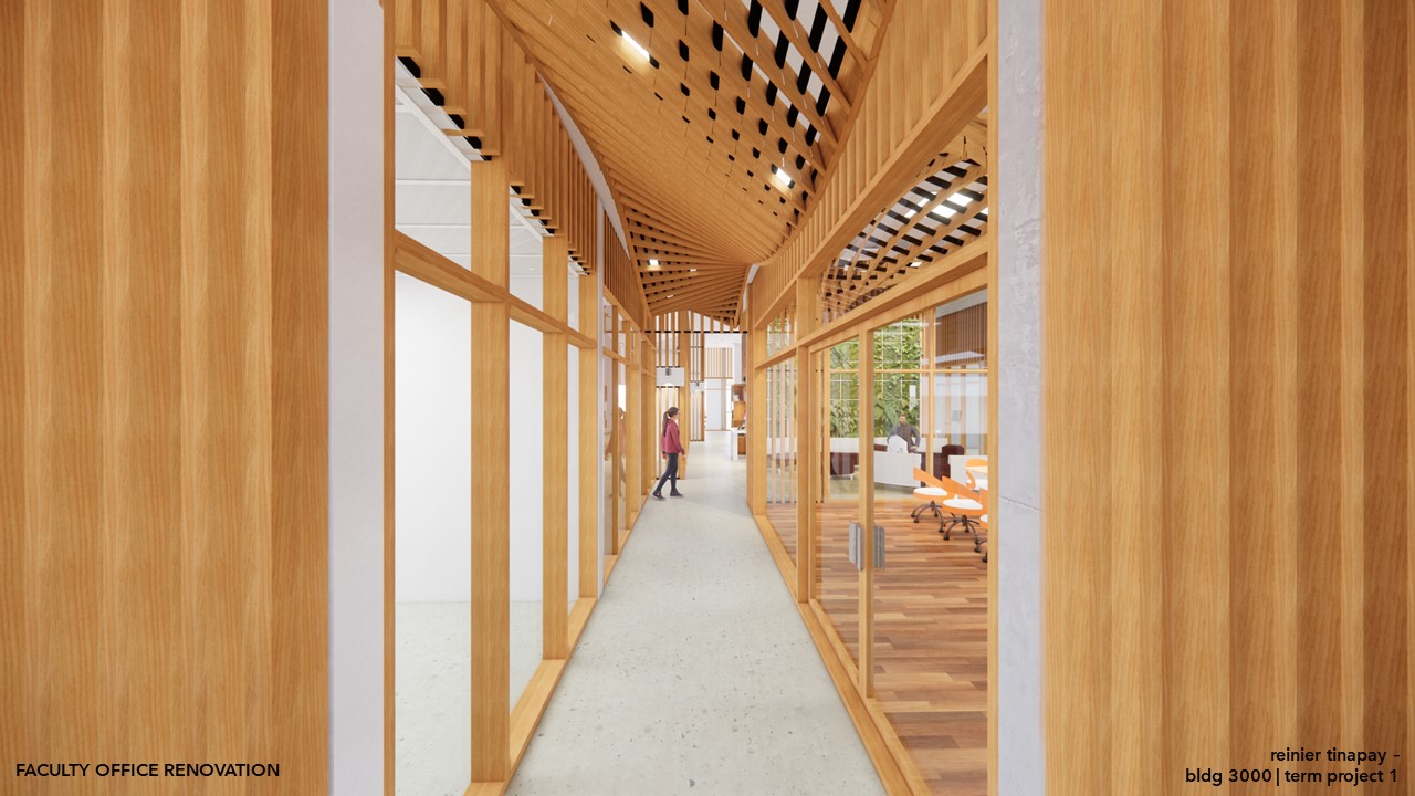
For this proposal, we created a tree floating dome shape back-lit by an egg shaped light to create the feeling of floating and allow for a feeling of ‘komorebi’ or light penetrating through leaves (or the tiles in this case).
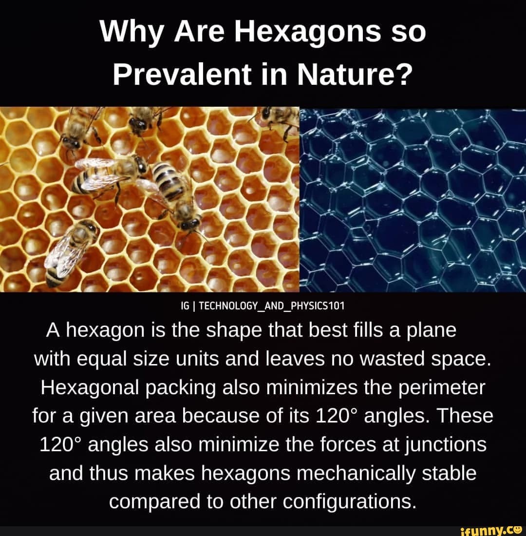
Lastly, I leave you with an interesting tid bit about hexagons.
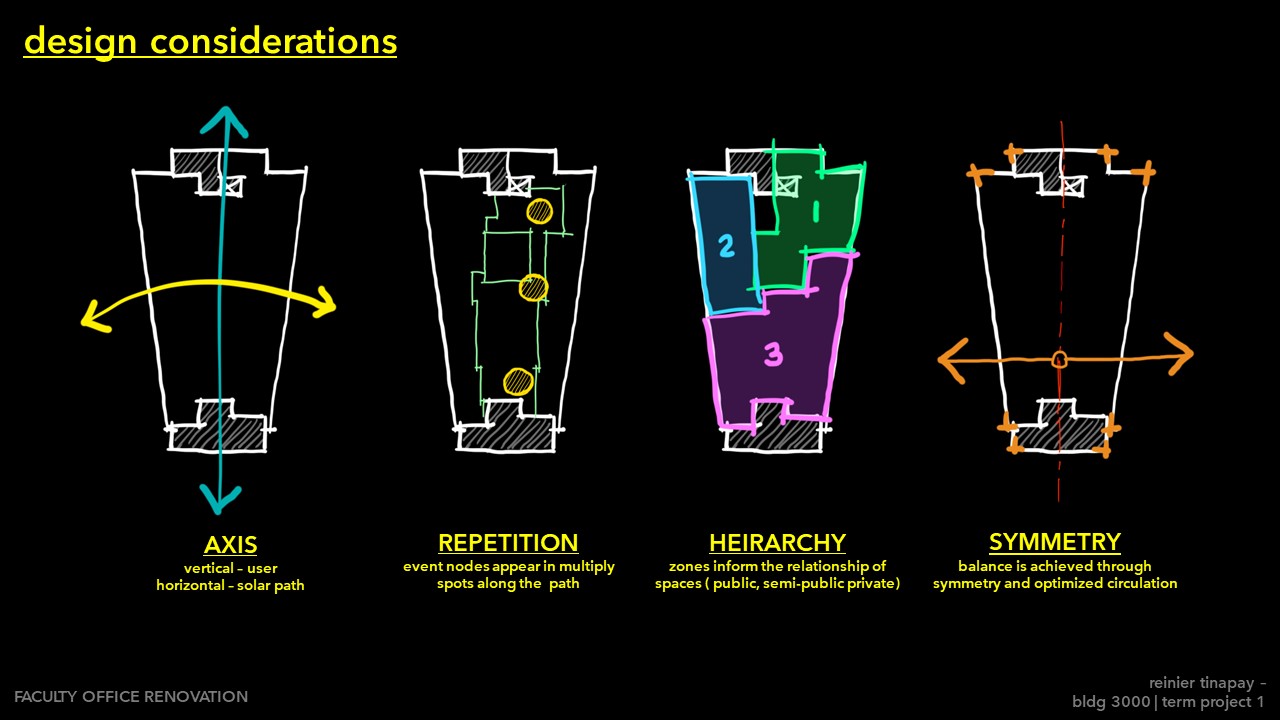
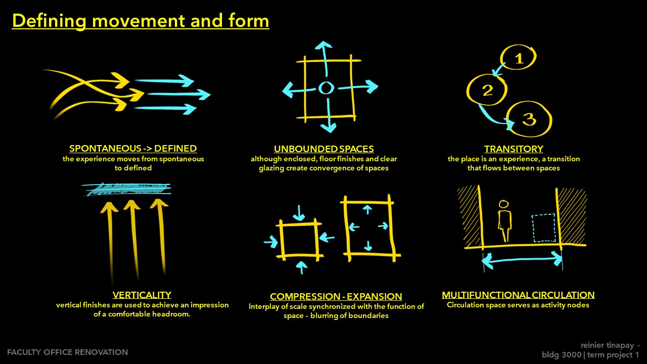
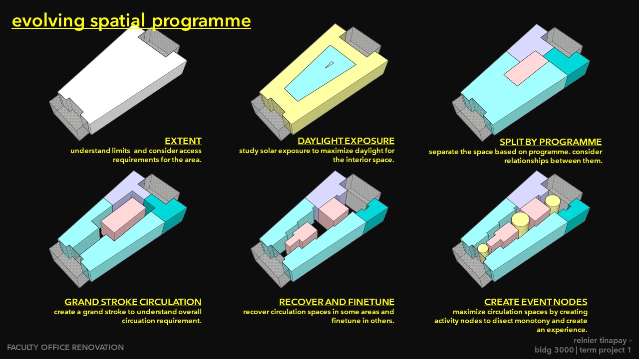
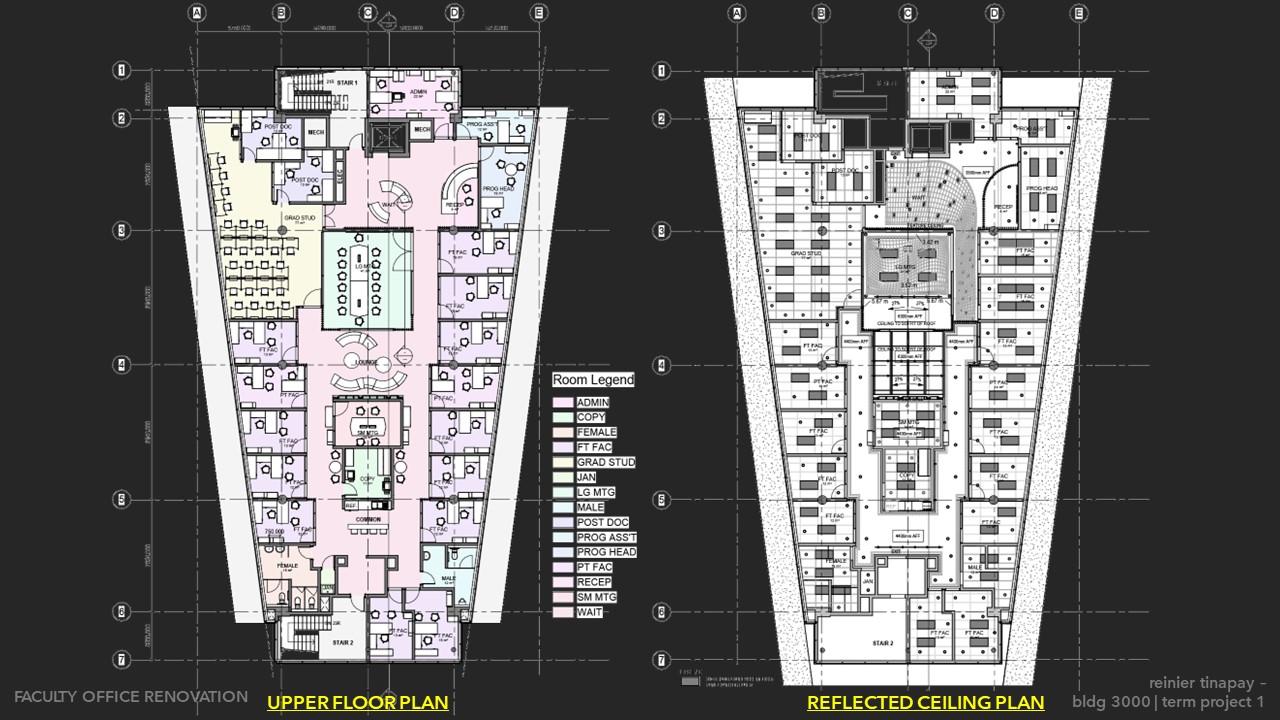
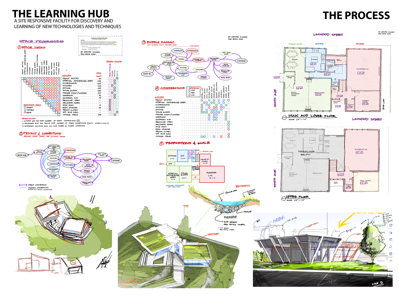
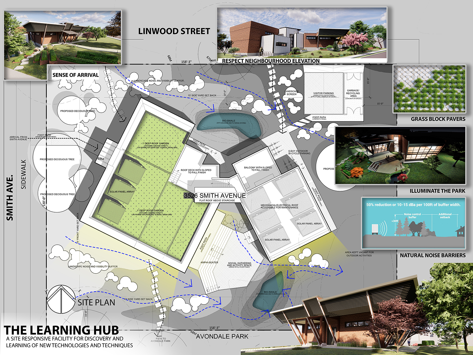
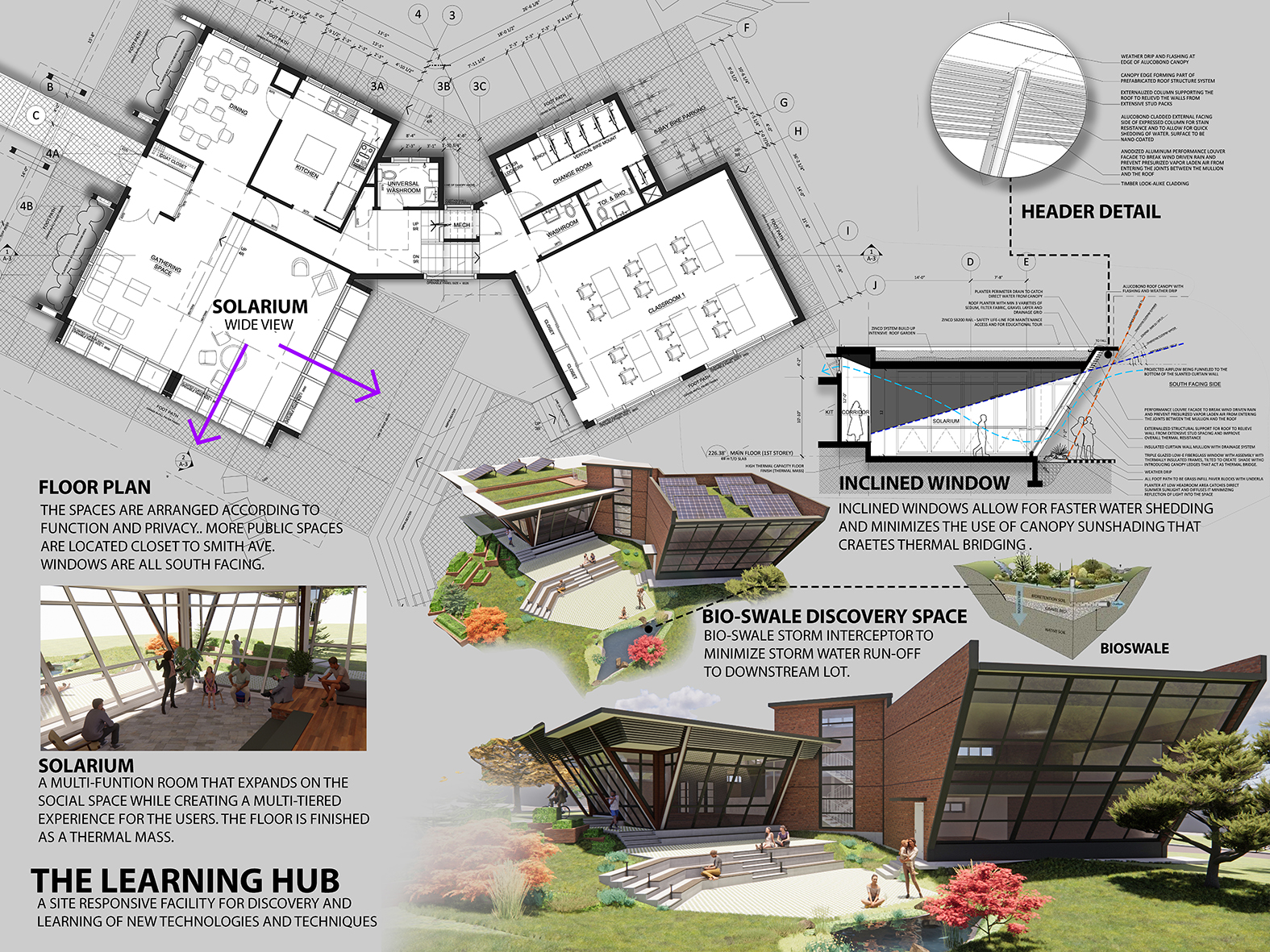
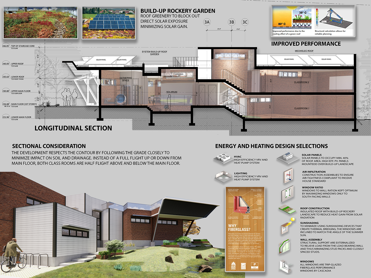
A study on form and programme, on how spatial relationship define how functions can be expressed. Focused on key compositional concepts and utilized advanced parametric modelling tools.


Revit file here : https://we.tl/t-OdxzzxuwUW
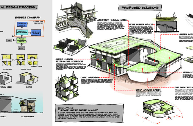
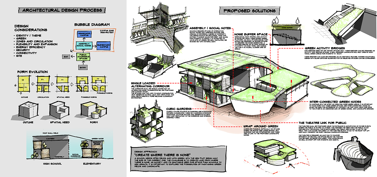
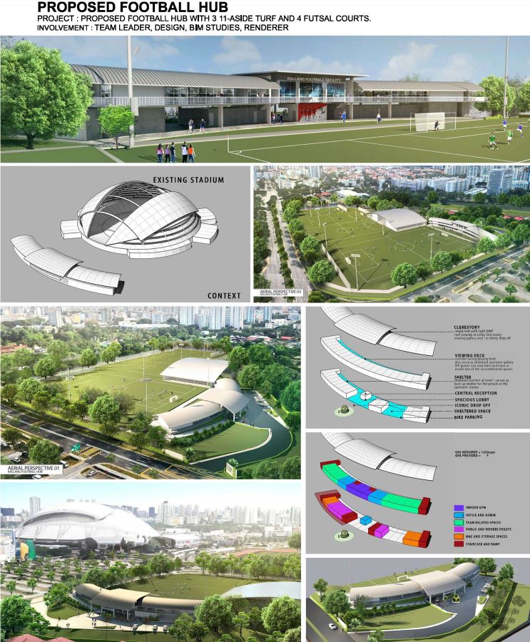
Architectural design and programming study
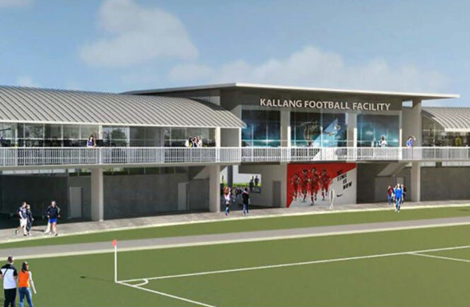
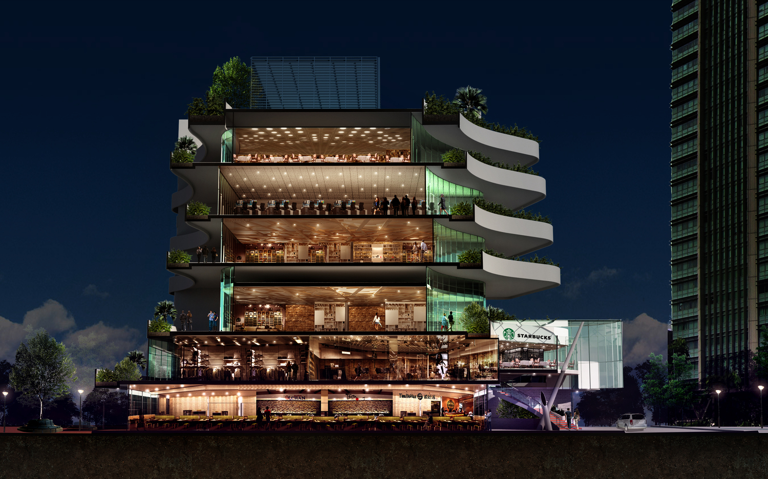
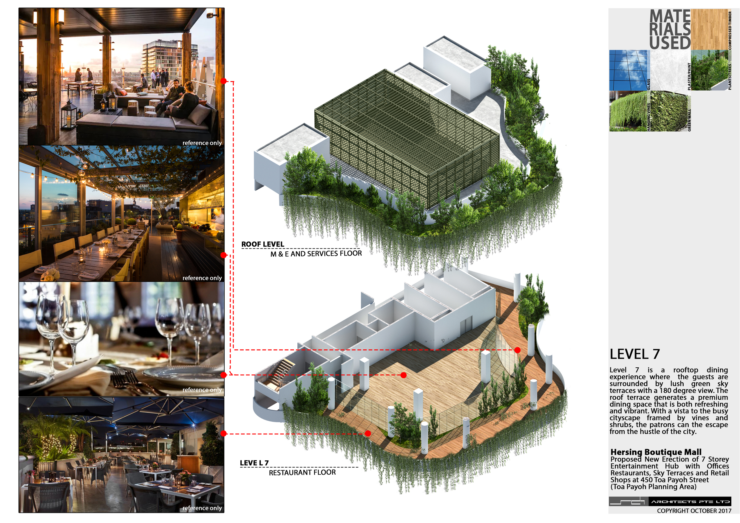
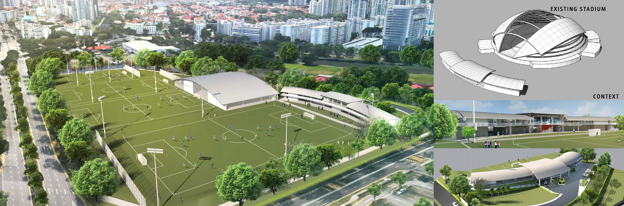
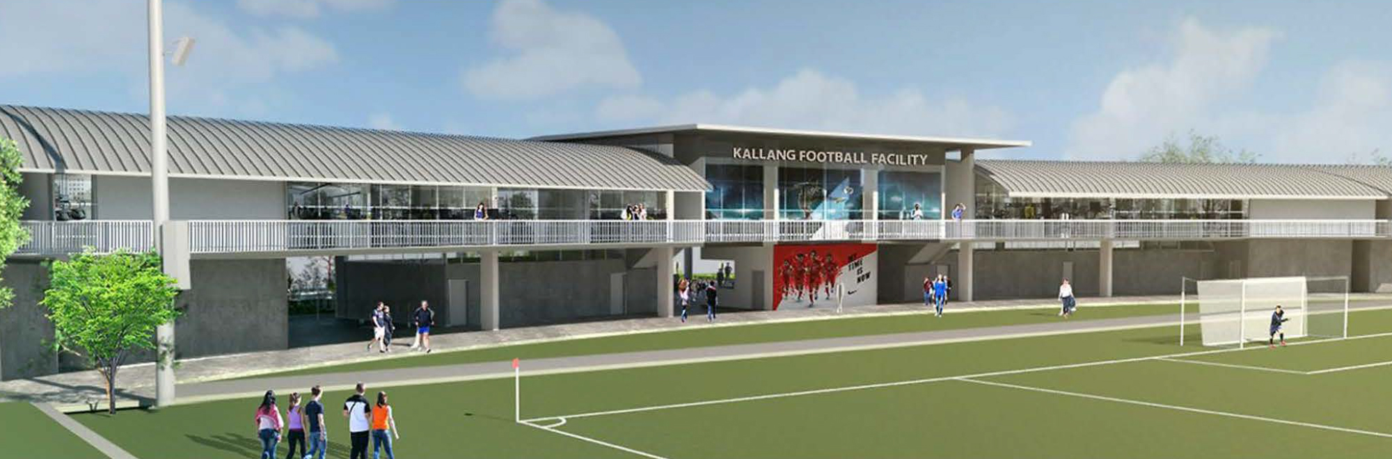
Proposed I5.2 hectare sports and recreation complex
Involvement : Led a successful design tender campaign to secure a 5.2-hectare sports and recreation complex. During the competition, I managed a team of associates to come up with a compelling design proposal that managed to convince the client to select our team for the project
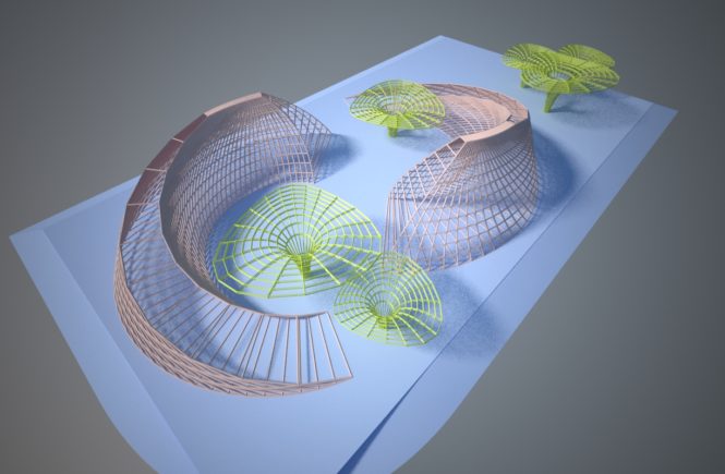
There is something about how fishes swim around each other in the symbol of Yin and Yang. Although I have never observed this in nature, it has been well observed that fishes swim in groups and that they often swim about in ever changing direction.In my road to improving my skills in conceptual presentation, I explored the form of the Pisces as a concept art.
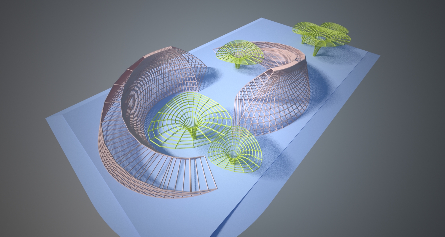
It started out as a concept model on 3d max.
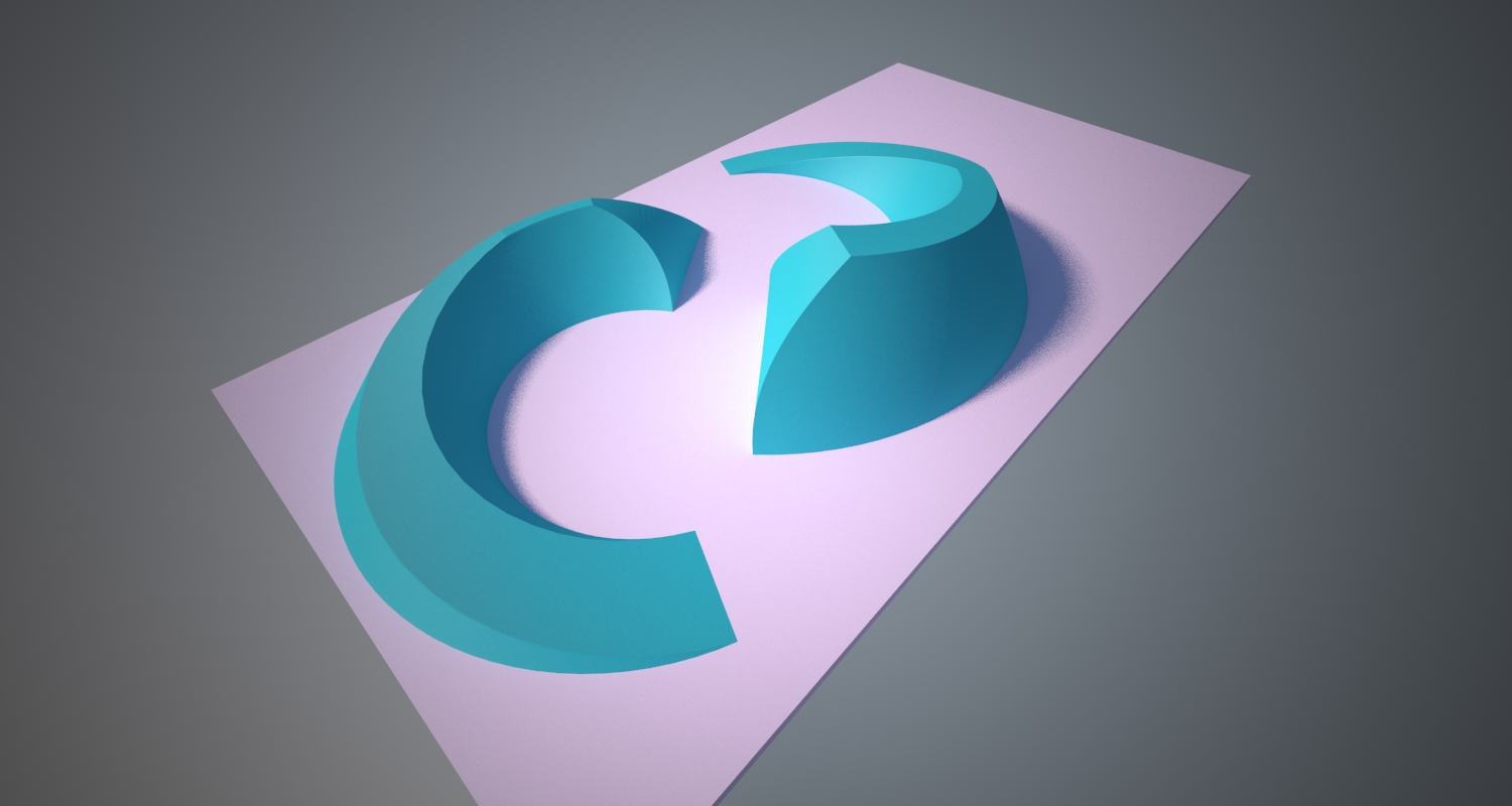
later on, I added a few lillies and changed the colors around to better reflect the story. The base shape is now showing two fishes swimming about in a pond with water lillies around them.
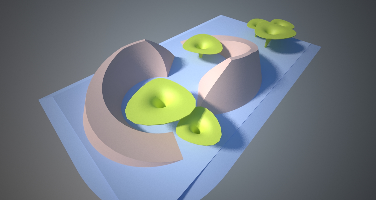
This later evolved into a latticed version where it can be constructed with frames and frames of timber or steel members.
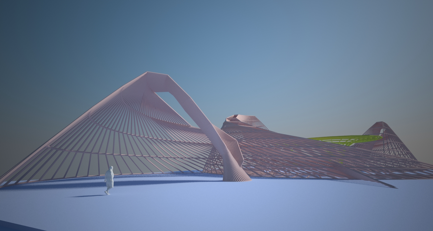
and finally, a mans eye view of this pavillion concept art.
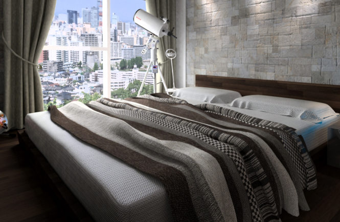
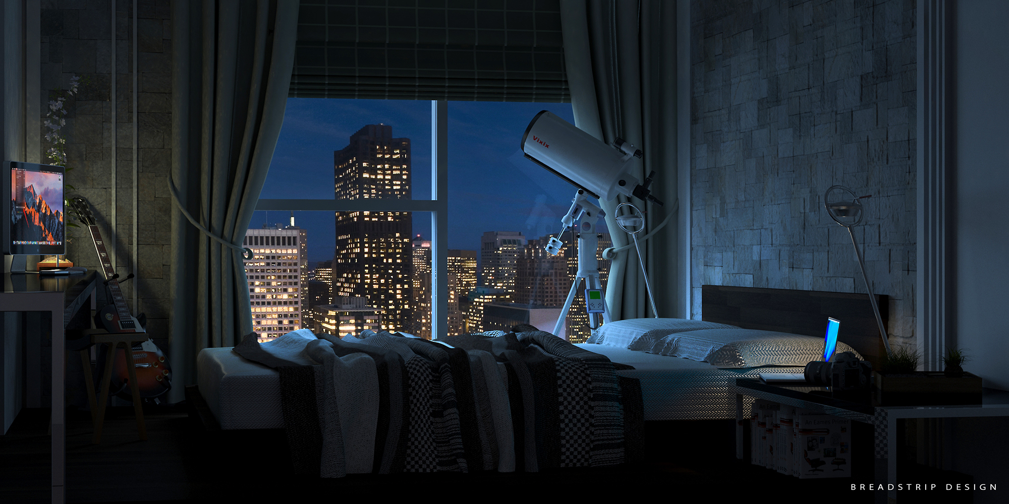
A quick 3d modelling and rendering exercise with 3ds max and Vray.
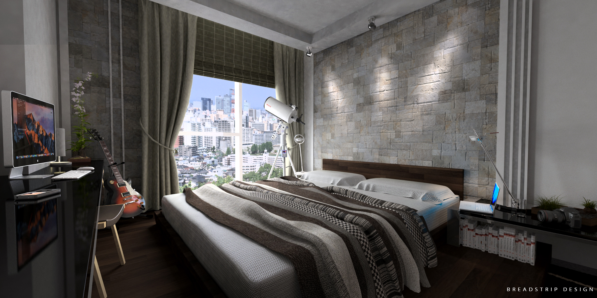
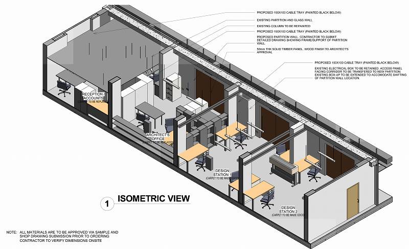
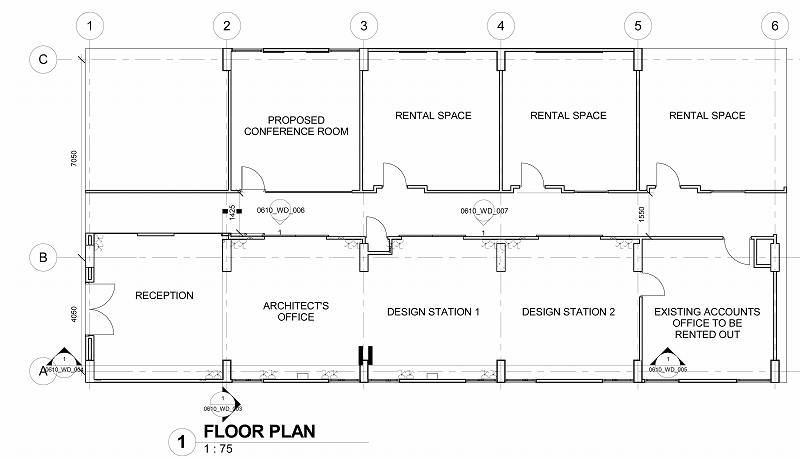
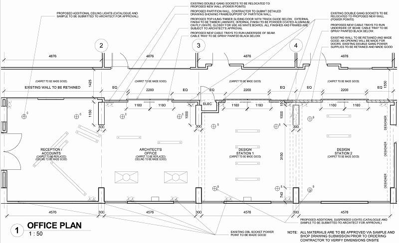
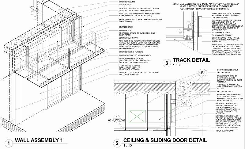
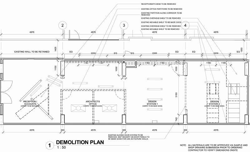
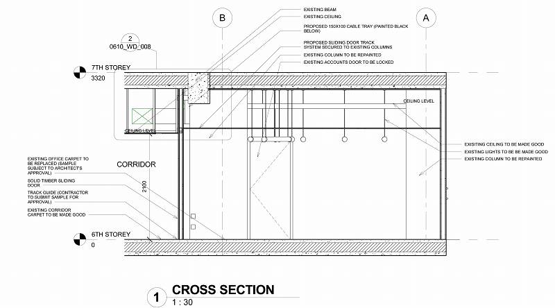
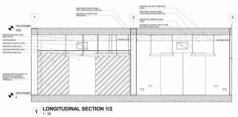
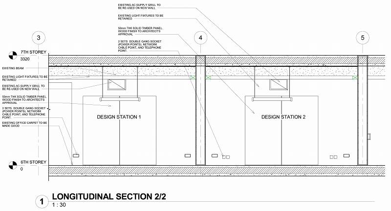
Revit is a powerful design visualization tool. But once in a while, I try to see just how much detailing I am capable of doing within its environment. Apparently, it can be as detailed as autocad too.
The illustrations and specs below are done entirely in Revit.
The following is An excerpt from a paper on BIM for compliance of Handicapped Routing by Reinier Tinapay.
ABSTRACT
Current CORENET E-Submission Guidelines lack the template, tools, families and parameters that assist in creating a more intelligent means of generating Accessibility-Compliant Models. As such, there is a tendency to revert to 2D methods to generate lines, paths and regions for routings. This 2d method is counter-productive.
The Aim of this project is to explore, design and develop a compact BIM tool to improve productivity in utilizing BIM for modelling a BCA handicapped routing compliant model. Using Autodesk Revit as the Authoring Software, the project maximizes pre-loaded tools such as schedules, conditional formatting and shared parameters to create a family that can be used as a checking and measuring tool for handicapped routing requirements.
The result is a quick and reliable tool for measuring gradients, and routing clearances using a parametric 3d family. Due to its parametric customizability, it can also be used for measuring pipe run gradients, storm drain gradients and even staircase run-rise ratio.
The study concludes that a parametric 3d family greatly improves efficiency. A significant amount of modeling time is saved when compared to annotating inside a view. This time-saving results in improved productivity.
ADAPTIVE COMPONENT FOR ROUTING
This study proposes standardizing the modelling procedure for BCA handicap routing using easy to adapt tools that can be used inside the 3d environment. It attempts to harness in-built tools of Revit to create a parametric family capable of automatically detecting and high-lighting non-compliant ramp gradient (maximum 1:12) as well as creating a schedule of lengths and gradients. This family can be integrated into submission templates or prepared as an add-on pack.
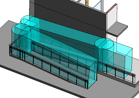
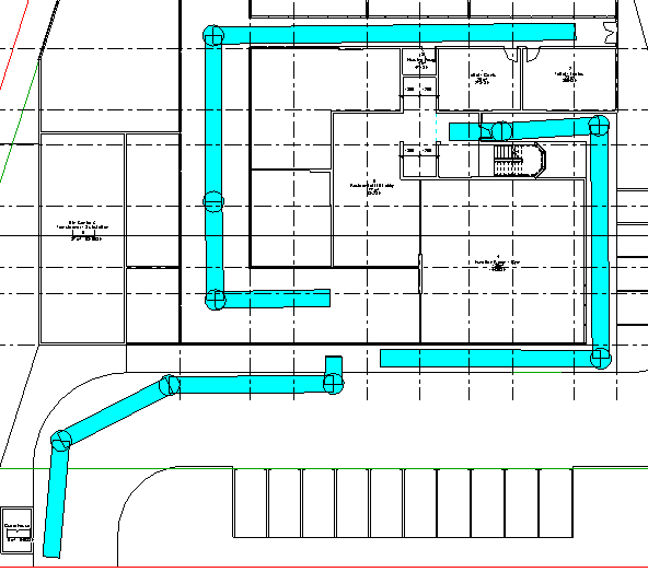
Using this adaptive component family, the study aims to create a routing plan for the project model to verify that it is compliant to authority requirements for Accessibility. The ‘routing.rfa’ will be modelled as a 3d element therefore it can be examined on all views. It will highlight by colour coding compliant versus non-compliant segments of the route (figure 1 and 2). And ultimately, the information gathered from the family will be prepared in such a way that it can automatically be scheduled for preparation of a submission drawing. Additionally, this routing can also be used for interference checks (figure 3) to identify any non-compliance in headroom requirements.
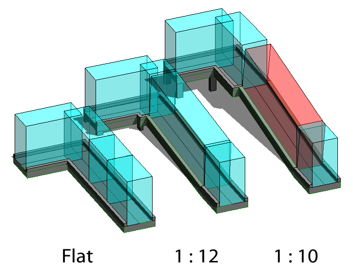
The Figure shows how the routing would show color coding when tested on different configurations of ramp gradients.
Showing a ramp complying with handicapped routing maximum gradient of 1:12
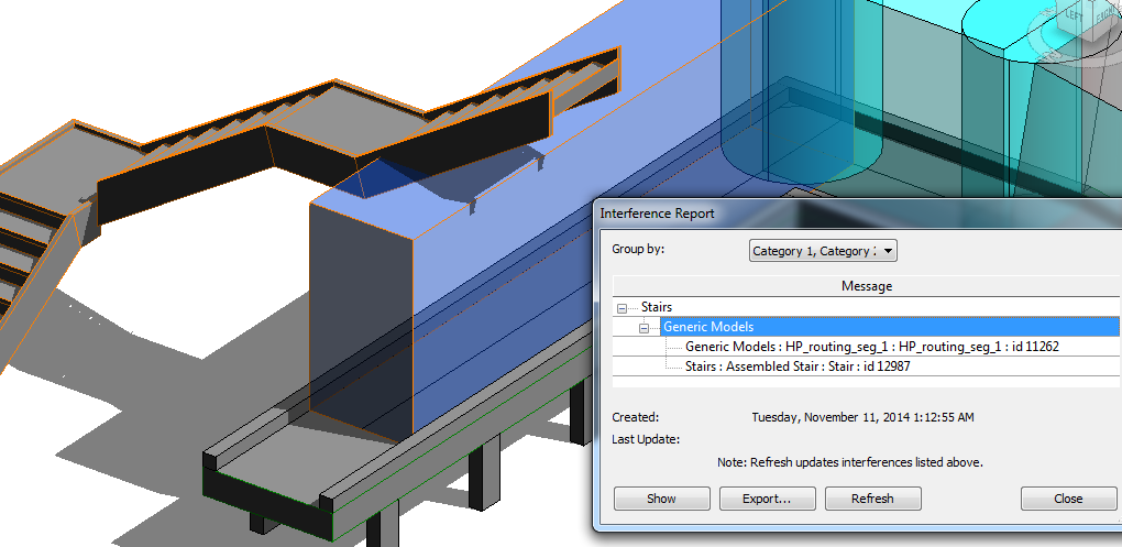
Using ‘router.rfa’ for headroom clearance using interference check
PROCESS OF DESIGNING THE ADAPTIVE COMPONENT
The ‘routing.rfa’ underwent a series of design study and testing before a final parametric solution was deemed acceptable and useful. A handful of considerations were made regarding rotational issues of the 3d elements within the family mainly because Revit segments made using reference lines connected by adaptive points behave in such a way that they rotate non-perpendicular to the surface at certain angles. This resulted in a routing segment that constantly flipped depending on the angle. In the initial stages of trying to solve this issue, parameters were made to control angular tilt but these angular controls can only hold up to a certain degree as Revit tends to shift angle location from one side to another choosing mostly, but not always, to dimension the acute angles. Ultimately, the design issues were resolved by nesting families of segments within the family. This method allowed all elements of the family to remain upright as the nested segments can be set to always point upwards from a plane.
Adaptive Component Nested Design
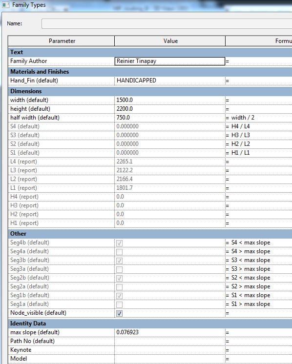
Parameters used in Adaptive Component
MILESTONES ACHIEVED IN THE DEVELOPMENT OF THE PARAMETRIC ADAPTIVE COMPONENT
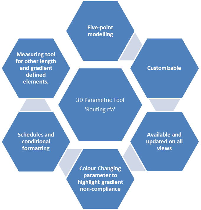
Using the framework that defined the problems faced, the goals set, and the experimentations with various means of measuring, the project has managed to develop an adaptive component family (routing.rfa) that can be hosted on any surface. This parametric component is capable of creating a 3d extruded segmented block with measureable attributes that can be used to generate a schedule. This 3d Parametric tool was then deployed on the Team’s Project Model for verification and measurements
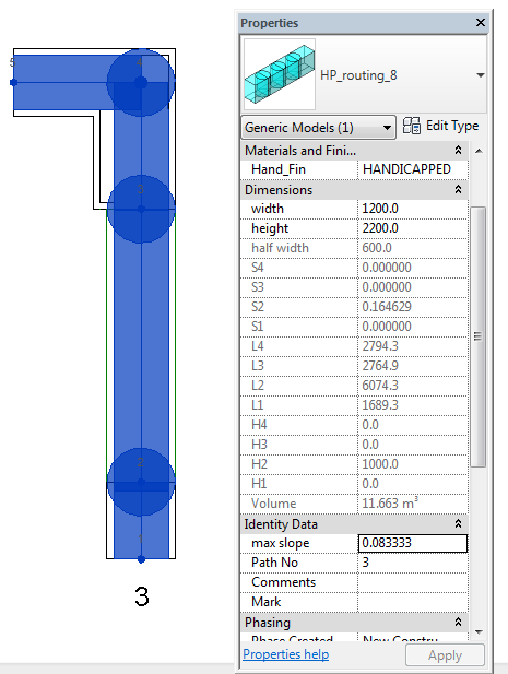
The routing.rfa was designed to be flexible and customizable. It can be reconfigured to suit any clearance and gradient requirements. Height, width and node visibility can be configured at the properties panel. The numeric values of these attributes are shared parameters therefore it can be used in schedules. Its dimensional attributes can be modified to match various authority or presentation requirements. It can be 2.2 meters tall for head room clearance. It can also be thin and flat for presentation purposes.
The component is a 3d solid with transparency set to allow it to be drawn on the model without blocking the objects behind it. This gives the modeller a better understanding of the ‘routing.rfa’s relationship to the elements around it. Likewise, since it is a 3d component, it can be drawn on plan or 3d view and will accordingly appear in all views. Compared to conventional means where the annotations are done on selected plan views, this method allows the user to examine the routing in a 3d context. This opens up a lot of possibility for analysis and design studies.
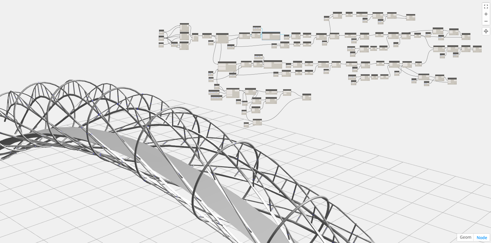
Revit and other BIM softwares are at the forefront of Parametric modelling. And with the advent of iterative modelling made possible by code block based systems such as Dynamo, it has become easier for architects and designers to experiment with shapes and designs.
here are some of my recent works with Dynamo.
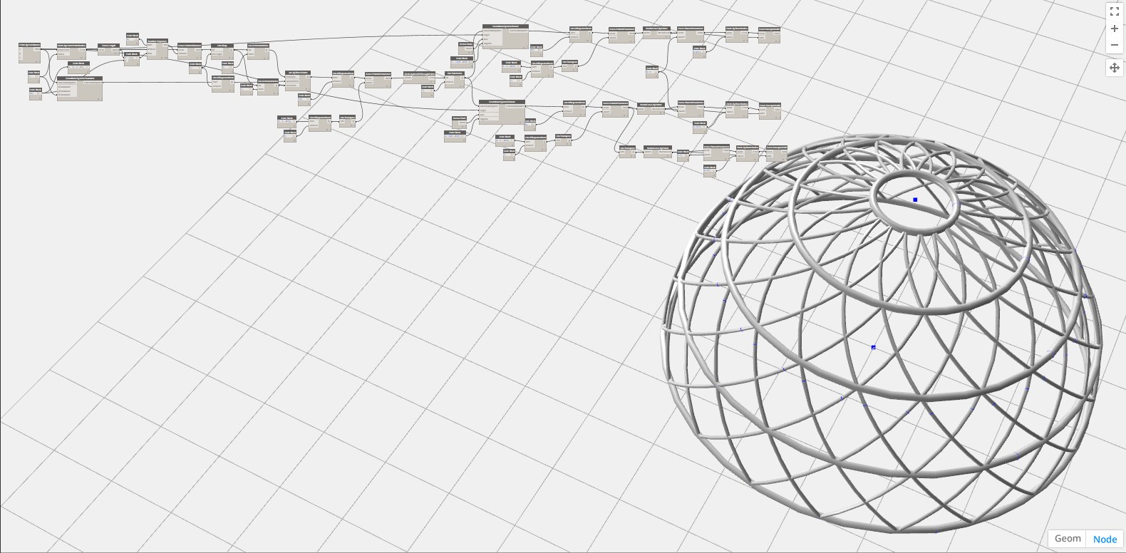
parametric dome. adjustable elevation, radius and number of rings.
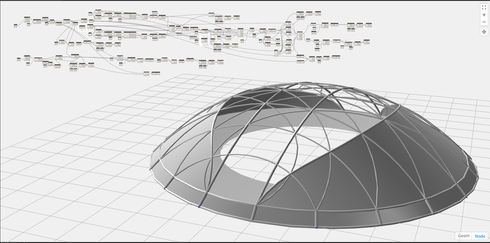
a sports dome. parameters for stadium apex height as well as other functions are adjustible
a study on helix modelling. trying to get a better understanding of how listing works.
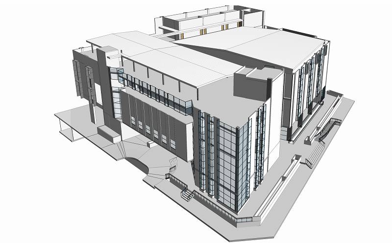
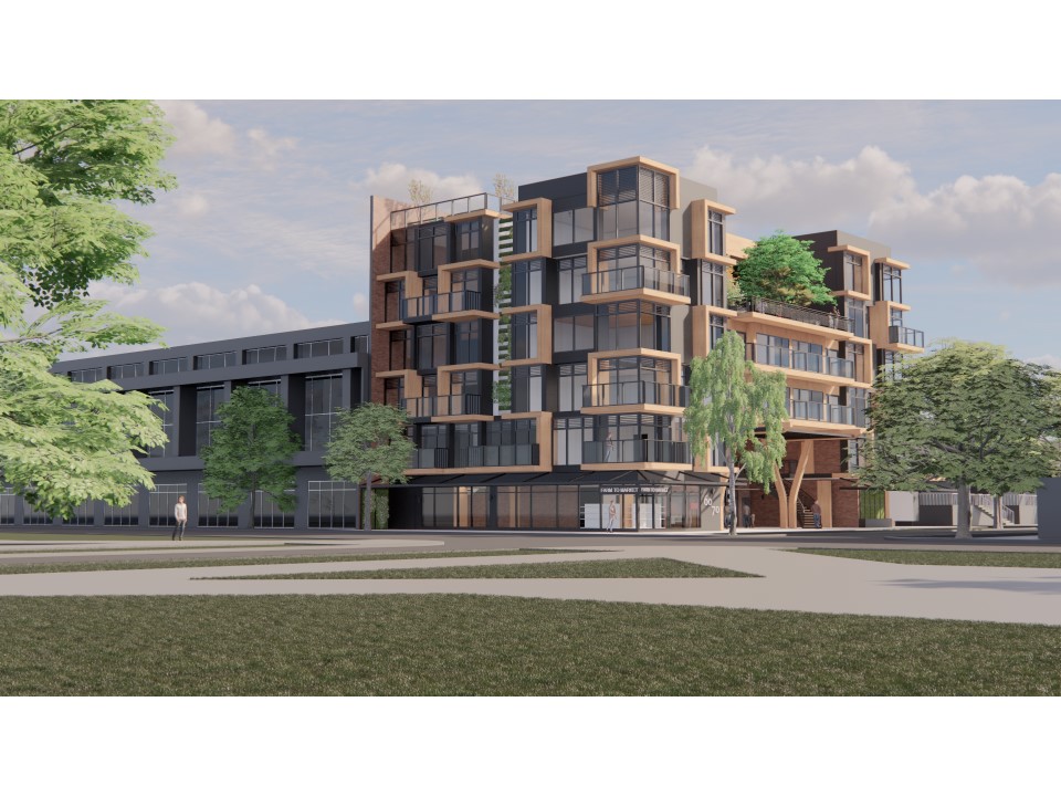
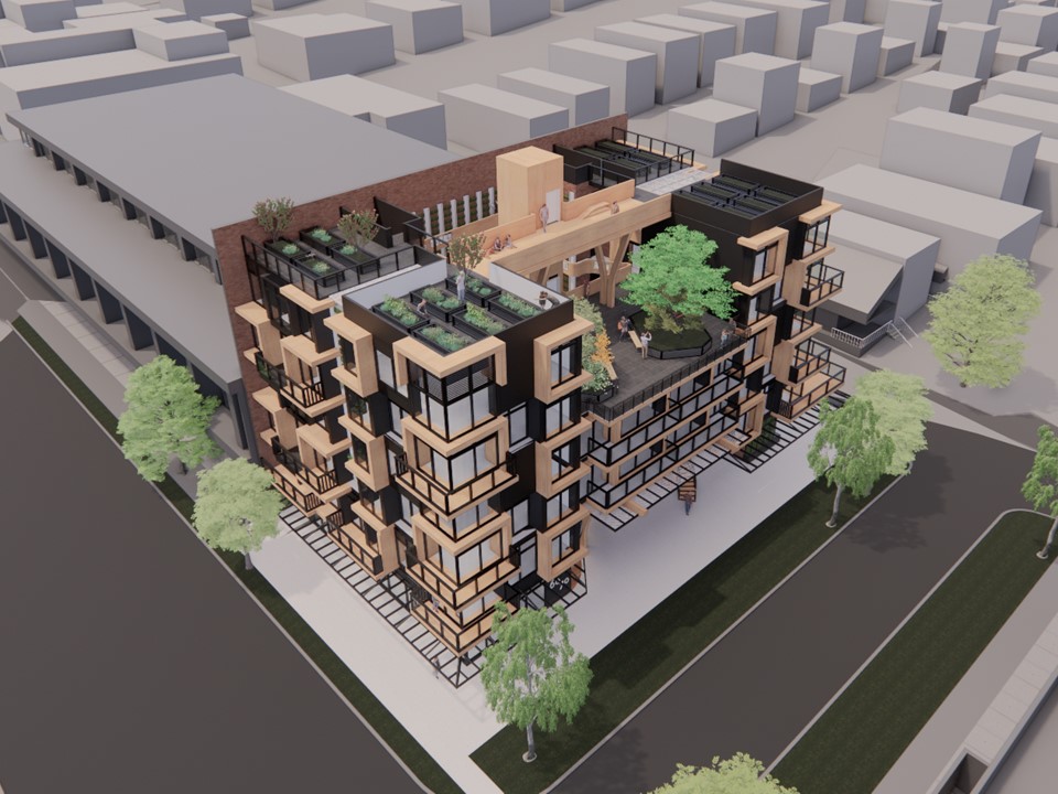
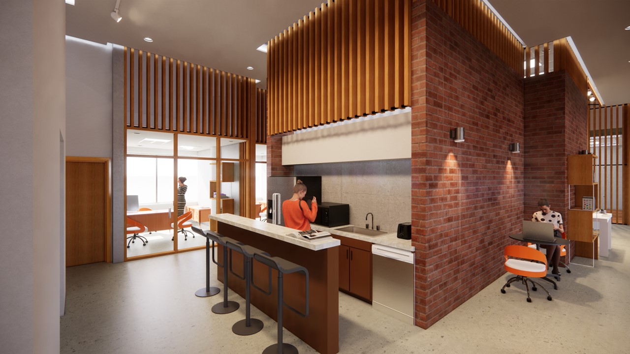
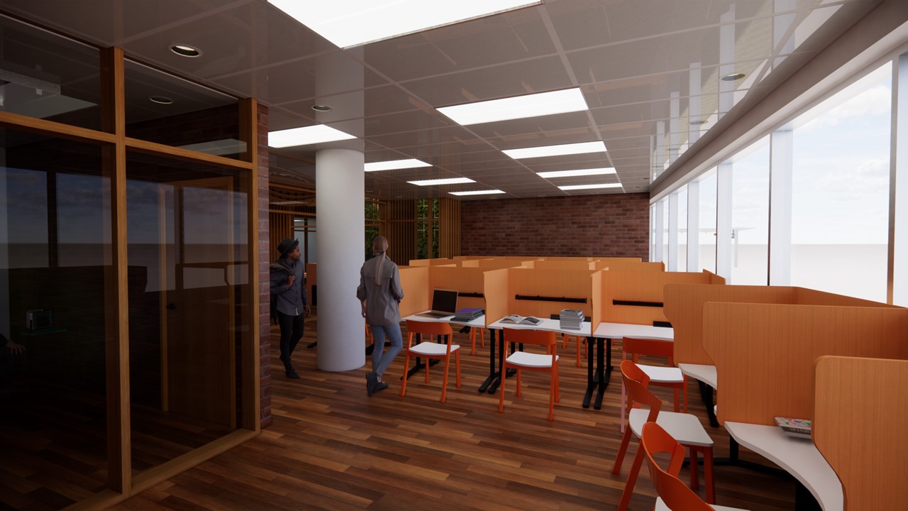
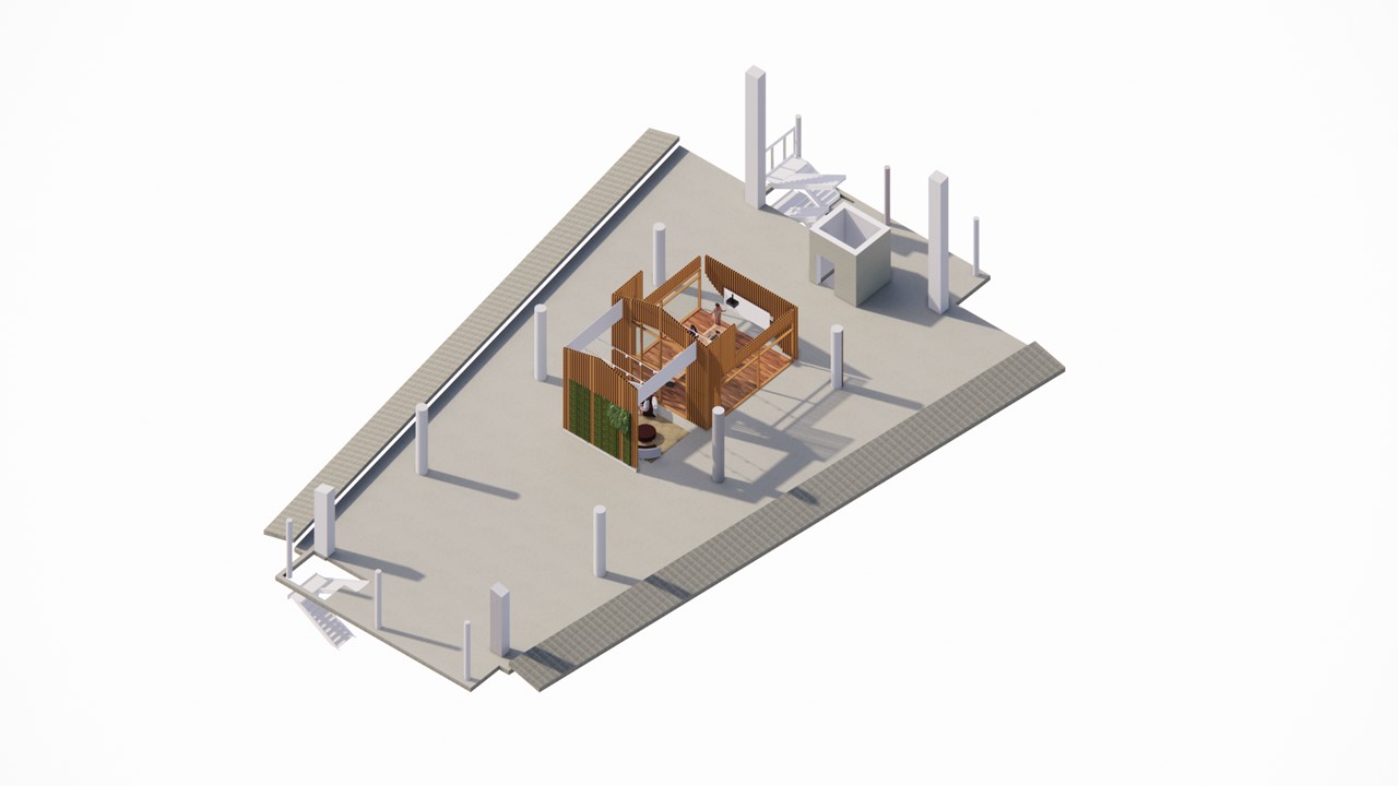
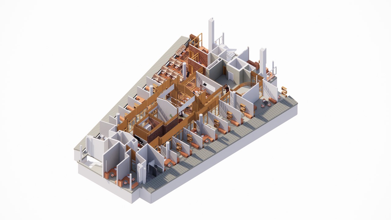
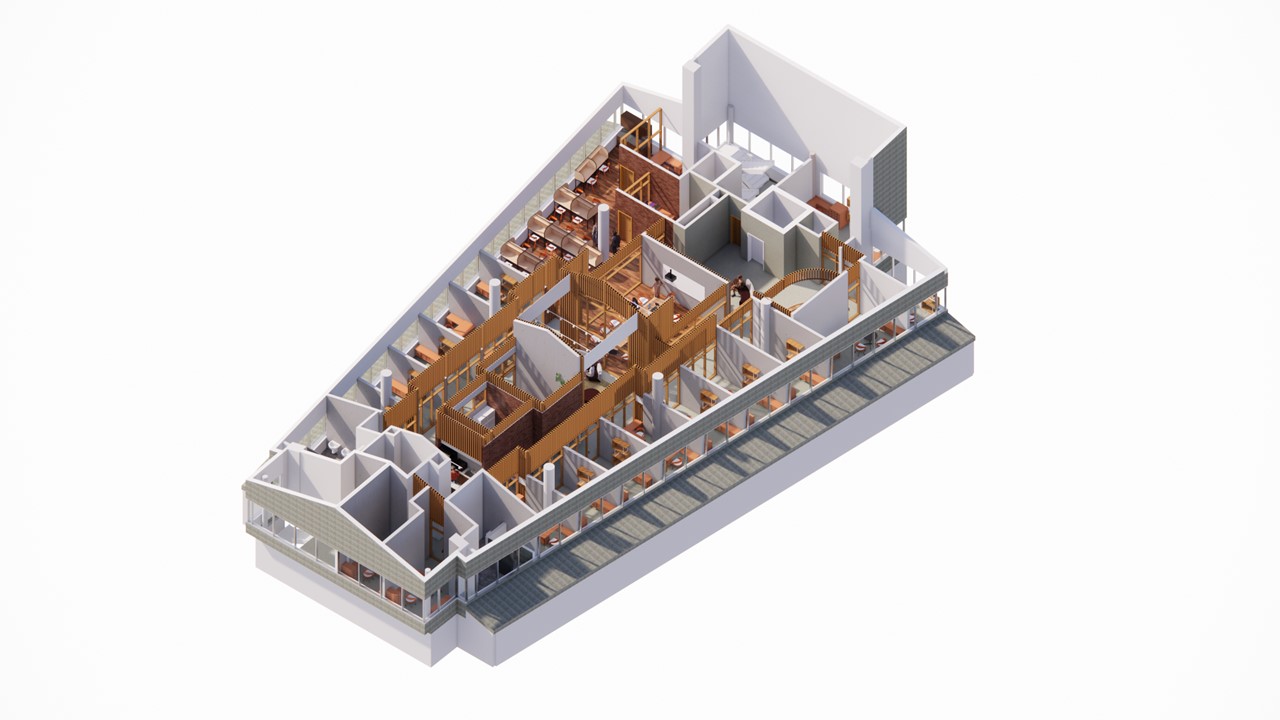
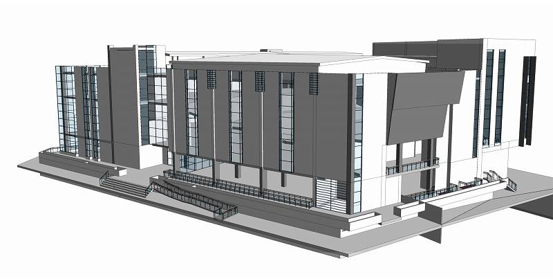
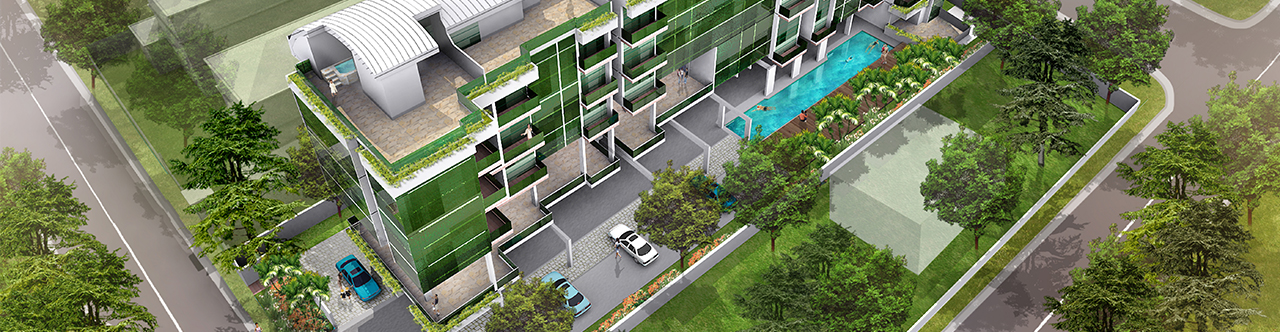
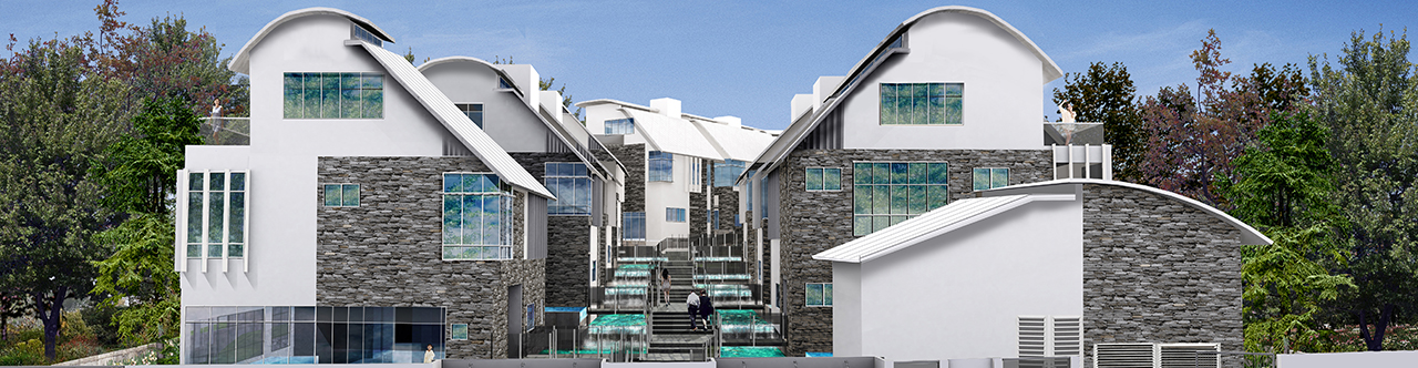
Revit is a powerful design visualization tool. One of the very useful tools available for designer is the Design Options tool. This allows the designer to create multiple iteration of a certain design by changing portions of the model within the same project model. This allows for time saving compared to modelling an entirely new model as optionas any changes made that are applicable to both options can be shared.
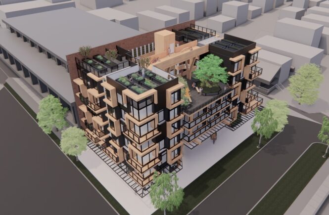
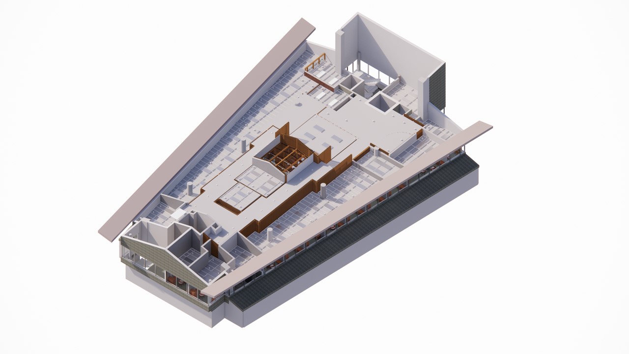
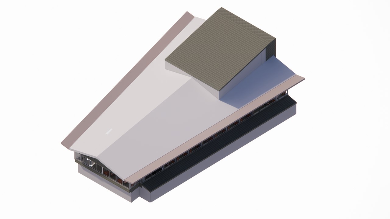
Below is a sample project we did….the first four images show the entire project in its option 1 stage. The last 2 photos are showing part plan and part perspective to emphasize the design options.
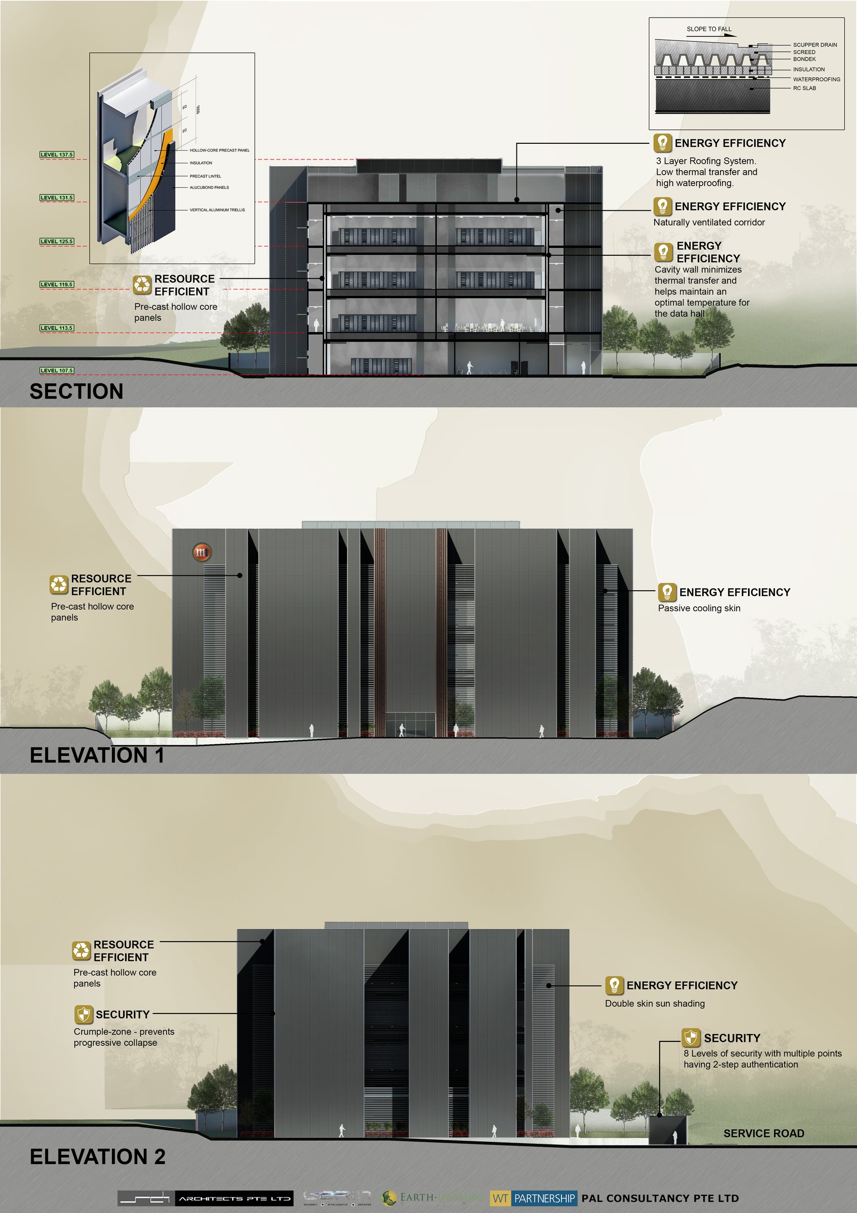
ELEVATION 1&2
ELEVATION 2 & 3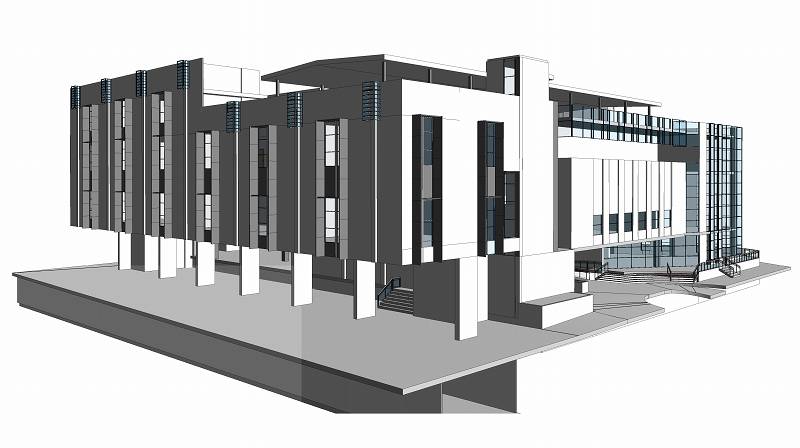
ELEVATION 3 &4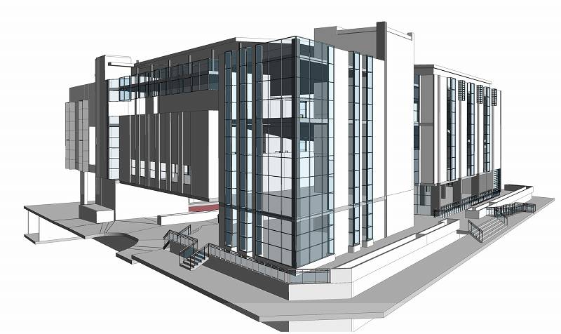
ELEVATION 4&1
When client requested a slight design variation for option, we modelled the variation using Revit’s Design Option tool.
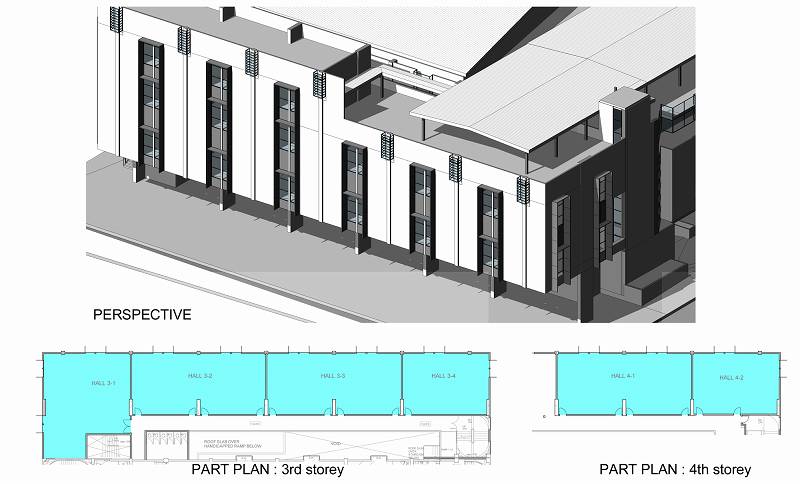
OPTION 1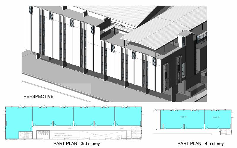 OPTION 2
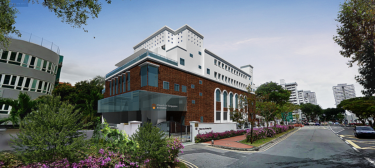
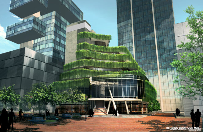
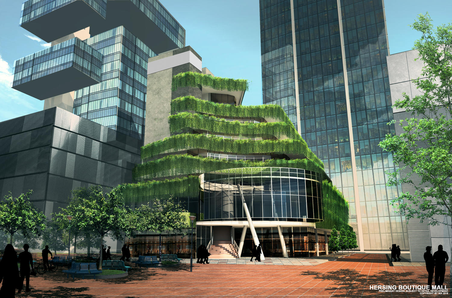
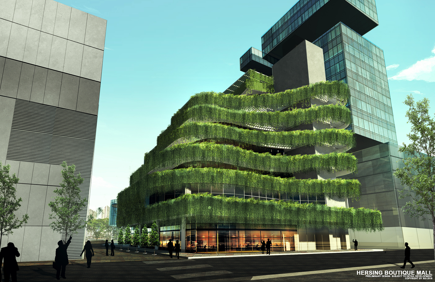
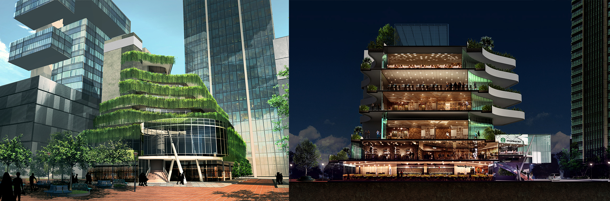
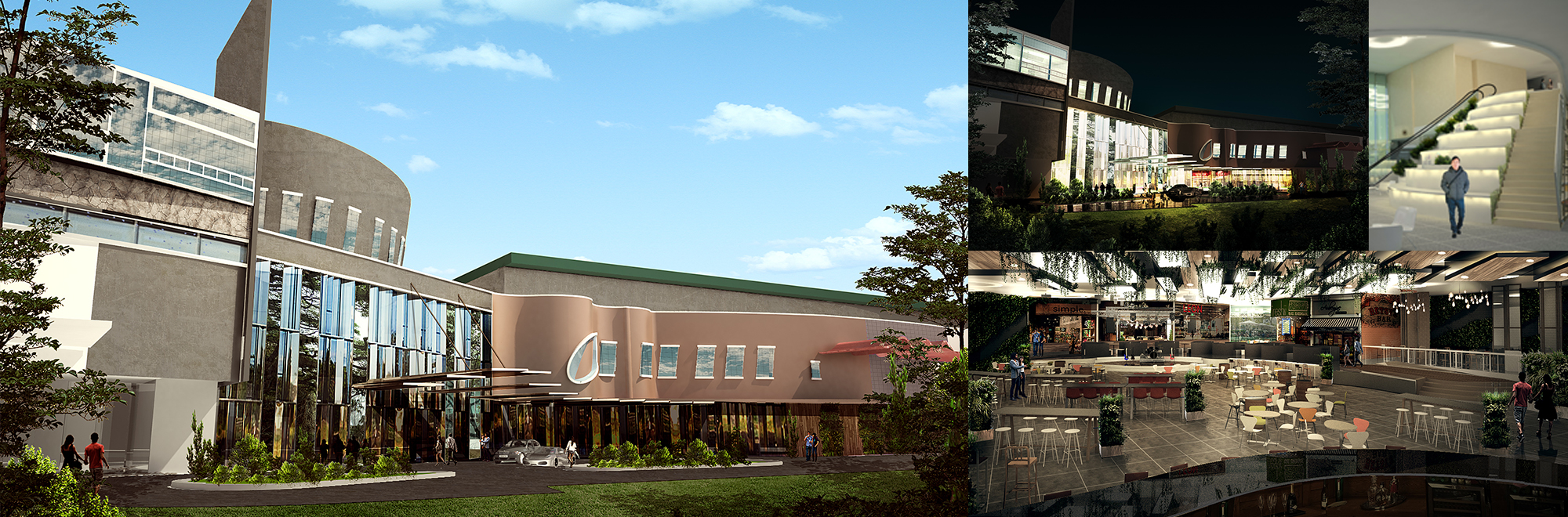
A peek of some of the rendering works I’ve done with 3d Max.
CHURCH OF SINGAPORE
 HOTEL GRAND CENTRAL
 CEYLON COURT