Modeling Helix Bridge in Dynamo

helix 2

helix 3

I started this modelling study with much enthusiasm, sustained it with an abundance of curiosity and finished it with great relief. With neither training nor knowledge on using Dynamo, I leapt right in armed with hours-upon-hours of reading and video materials contributed mainly by the scholastic generosity of people from world-wide-web.

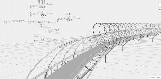
I decided to use Singapore’s iconic Helix bridge as my platform for learning. I downloaded and studied plans, elevations and illustrations available online to get a better understanding on how the bridge was designed. The steps below does not aim to be a tutorial, but rather a means document my endeavors. There are far better methods and shorter ways out there that I for one am eager to learn. Just as well, this study does not attempt to copy every detail of the bridge, but only aim to model the general features of the bridge using the basic code blocks that I’ve learned in the process.

015281e956a770bbe54eac25837ea460
illustration taken from google image search
helix diagram
simple section done in Autocad

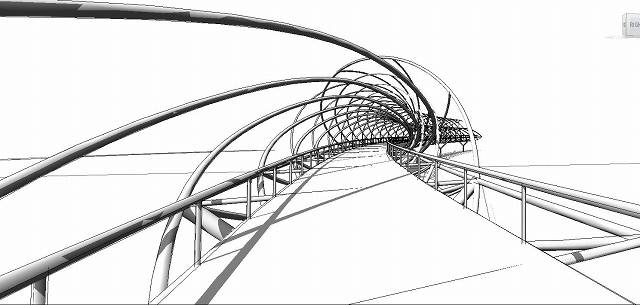
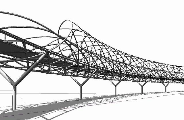
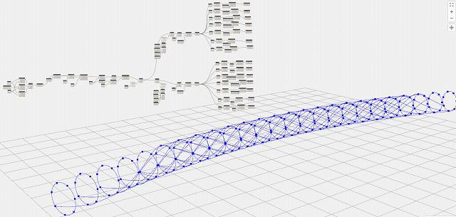
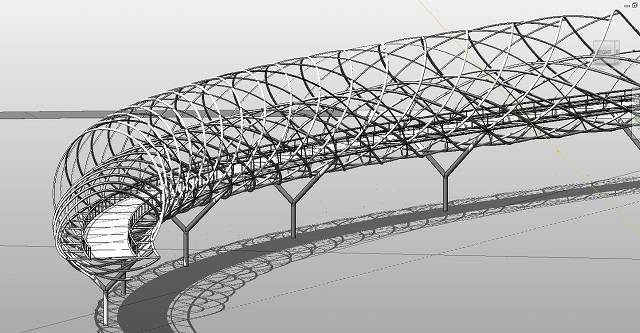
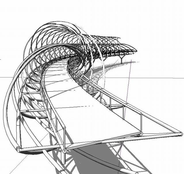
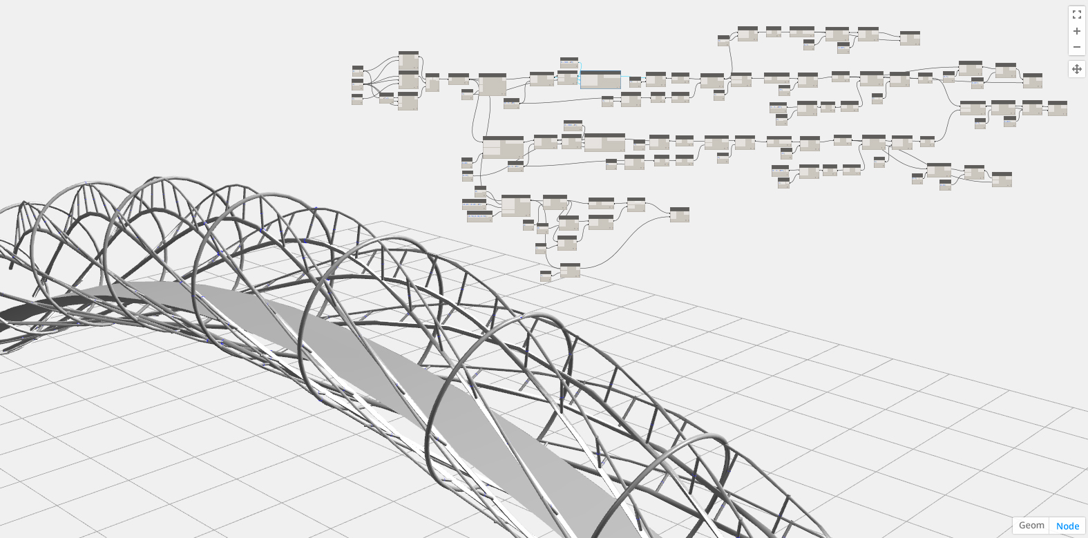
The bridge is composed of 2 major helix strands. The first strand is the outer shell which is circular in section. The second is an elliptical in shape embedded within the circle with half of it an overlapping arc with a portion of the circle.

01

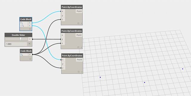
begin modelling with 3 independent point representing the middle and ends of the bridge. These 3 points can be manipulated manually even after the succeeding parts are put in place.

helix tutotial 1

String a nurb.curve across the 3 points and use plane by parameter to generate a series of planes that run across the entire curve. These planes will be hosted on the curve therefore it will constantly adjust itself according to the curve profile. Using circle on plane radius, generate a series of circles on all planes.

 helix tutotial 2

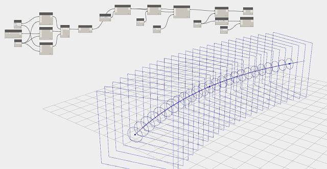
Generate points across all the circles using point parameter. Using shift index, I shifted each of the points grouped along the circle by one point at each step. This makes the points rotate around the circle by 1 index at each ring. Using list transpose, I am able to generate nurb curve across all points to create the helix above.

 helix tutotial 3

Now it’s time to carve out the ends of the helix. The Singapore helix terminates with its curve finally resting on the base of the curve. Using get index, select each curve and use remove items at index to take out points at the end of the helix .

helix tutotial 4

Repeat the same process above but reverse the shift index. Once again, select each curve and remove the points to give the end its shape.

helix tutotial 5

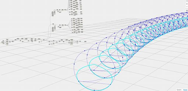
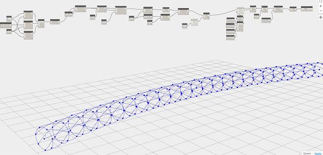
Create the minor helix strand using 2 of the points at the base of the major helix strand. Do this by translating the center points to create the top and bottom and then creating a list with it and the 2 basepoints. Use curve by point tool to generate the curve.

helix tutotial 6

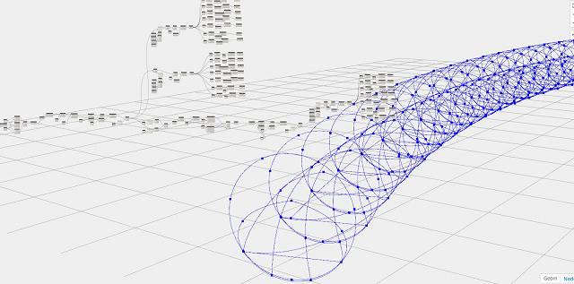
Using the same process above, generate points and run curves across these points. Trim the ends again to make the bridge termination.

helix tutotial 7

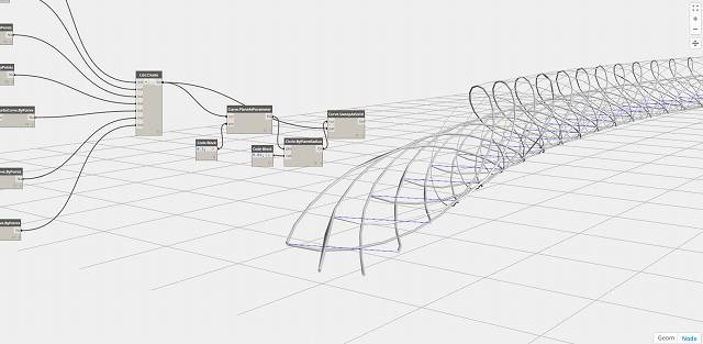
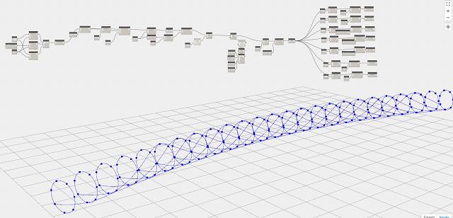
Generate 3d sweeps across the curves. In this process, I created planes parameter and set the parameter at 0.5. Created a circle on that plane and sweep it across the curve.

helix tutotial 8

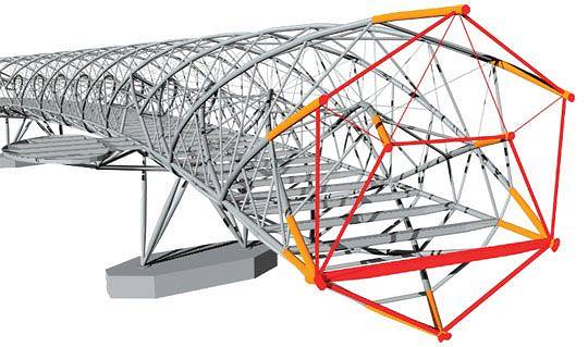
Now that the main helix is done, create the other accents to complete the bridge.

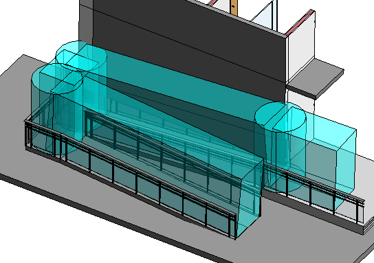
Here’s the bridge in Revit view.

helix 2 helix 1 helix 4 helix 3

Continue Reading

Detailing With Revit

Revit is a powerful design visualization tool. But once in a while, I try to see just how much detailing I am capable of doing within its environment. Apparently, it can be as detailed as autocad too.

The illustrations and specs below are done entirely in Revit.

Sheet - 0610_WD_001 - FLOOR PLANS

Sheet - 0610_WD_002 - OFFICE PLAN

Sheet - 0610_WD_009 - ISOMETRIC with furnitures color

Sheet - 0610_WD_008 - DETAIL OF SLIDING DOOR

Sheet - 0610_WD_010 - DEMOLITION PLAN

Sheet - 0610_WD_003 - CROSS SECTION

Sheet - 0610_WD_004 - LONGITUDINAL SECTION 1-2

Sheet - 0610_WD_005 - LONGITUDINAL SECTION 2-2

Continue Reading

Using adaptive component for performing routing check

The following is An excerpt from a paper on BIM for compliance of Handicapped Routing by Reinier Tinapay.

ABSTRACT

Current CORENET E-Submission Guidelines lack the template, tools, families and parameters that assist in creating a more intelligent means of generating Accessibility-Compliant Models.  As such, there is a tendency to revert to 2D methods to generate lines, paths and regions for routings. This 2d method is counter-productive.

The Aim of this project is to explore, design and develop a compact BIM tool to improve productivity in utilizing BIM for modelling a BCA handicapped routing compliant model. Using Autodesk Revit as the Authoring Software, the project maximizes pre-loaded tools such as schedules, conditional formatting and shared parameters to create a family that can be used as a checking and measuring tool for handicapped routing requirements.

The result is a quick and reliable tool for measuring gradients, and routing clearances using a parametric 3d family. Due to its parametric customizability, it can also be used for measuring pipe run gradients, storm drain gradients and even staircase run-rise ratio.

The study concludes that a parametric 3d family greatly improves efficiency. A significant amount of modeling time is saved when compared to annotating inside a view. This time-saving results in improved productivity.

ADAPTIVE COMPONENT FOR ROUTING

This study proposes standardizing the modelling procedure for BCA handicap routing using easy to adapt tools that can be used inside the 3d environment.  It attempts to harness in-built tools of Revit to create a parametric family capable of automatically detecting and high-lighting non-compliant ramp gradient (maximum 1:12) as well as creating a schedule of lengths and gradients. This family can be integrated into submission templates or prepared as an add-on pack.

Using this adaptive component family, the study aims to create a routing plan for the project model to verify that it is compliant to authority requirements for Accessibility. The ‘routing.rfa’ will be modelled as a 3d element therefore it can be examined on all views. It will highlight by colour coding compliant versus non-compliant segments of the route (figure 1 and 2). And ultimately, the information gathered from the family will be prepared in such a way that it can automatically be scheduled for preparation of a submission drawing. Additionally, this routing can also be used for interference checks (figure 3) to identify any non-compliance in headroom requirements.

image007

The Figure shows how the routing would show color coding when tested on different configurations of ramp gradients.

image009

Showing a ramp complying with handicapped routing maximum gradient of 1:12

image011

Using ‘router.rfa’ for headroom clearance using interference check

PROCESS OF DESIGNING THE ADAPTIVE COMPONENT

The ‘routing.rfa’ underwent a series of design study and testing before a final parametric solution was deemed acceptable and useful. A handful of considerations were made regarding rotational issues of the 3d elements within the family mainly because Revit segments made using reference lines connected by adaptive points behave in such a way that they rotate non-perpendicular to the surface at certain angles. This resulted in a routing segment that constantly flipped depending on the angle. In the initial stages of trying to solve this issue, parameters were made to control angular tilt but these angular controls can only hold up to a certain degree as Revit tends to shift angle location from one side to another choosing mostly, but not always, to dimension the acute angles. Ultimately, the design issues were resolved by nesting families of segments within the family. This method allowed all elements of the family to remain upright as the nested segments can be set to always point upwards from a plane.

image022

Adaptive Component Nested Design

image023

Parameters used in Adaptive Component

MILESTONES ACHIEVED IN THE DEVELOPMENT OF THE PARAMETRIC ADAPTIVE COMPONENT

image025

Using the framework that defined the problems faced, the goals set, and the experimentations with various means of measuring, the project has managed to develop an adaptive component family (routing.rfa) that can be hosted on any surface. This parametric component is capable of creating a 3d extruded segmented block with measureable attributes that can be used to generate a schedule. This 3d Parametric tool was then deployed on the Team’s Project Model for verification and measurements

image027

The routing.rfa was designed to be flexible and customizable. It can be reconfigured to suit any clearance and gradient requirements. Height, width and node visibility can be configured at the properties panel. The numeric values of these attributes are shared parameters therefore it can be used in schedules. Its dimensional attributes can be modified to match various authority or presentation requirements. It can be 2.2 meters tall for head room clearance. It can also be thin and flat for presentation purposes.

image029

image032

The component is a 3d solid with transparency set to allow it to be drawn on the model without blocking the objects behind it. This gives the modeller a better understanding of the ‘routing.rfa’s relationship to the elements around it. Likewise, since it is a 3d component, it can be drawn on plan or 3d view and will accordingly appear in all views. Compared to conventional means where the annotations are done on selected plan views, this method allows the user to examine the routing in a 3d context. This opens up a lot of possibility for analysis and design studies.

Continue Reading

Experimenting with Iterative Design

Revit and other BIM softwares are at the forefront of Parametric modelling. And with the advent of iterative modelling made possible by code block based systems such as Dynamo, it has become easier for architects and designers to experiment with shapes and designs.

here are some of my recent works with Dynamo.

dynamo dome
parametric dome. adjustable elevation, radius and number of rings.

dynamo sports hub
a sports dome. parameters for stadium apex height as well as other functions are adjustible

dynamo helix bridge
a study on helix modelling. trying to get a better understanding of how listing works.

Continue Reading