Lately, Ive taken a penchant for doodling and quick sketching. It has been so long since I last tried to draw anything, and since the last sketch I did for my previous post, Ive taken a habit of sketching everytime I have free time.
This post will be dedicated to all my quick sketches which I will compile from time to time. This is in a way, a means to document my journey to learn sketching and impressions.
IMPRESSIONS : STREETS AND HOUSES (coloured)
-a sketch on old houses and streets inspired by santorini
-sketched in 120gsm paper using Uniball Signo.
-Colored with tombow
-27 July2018

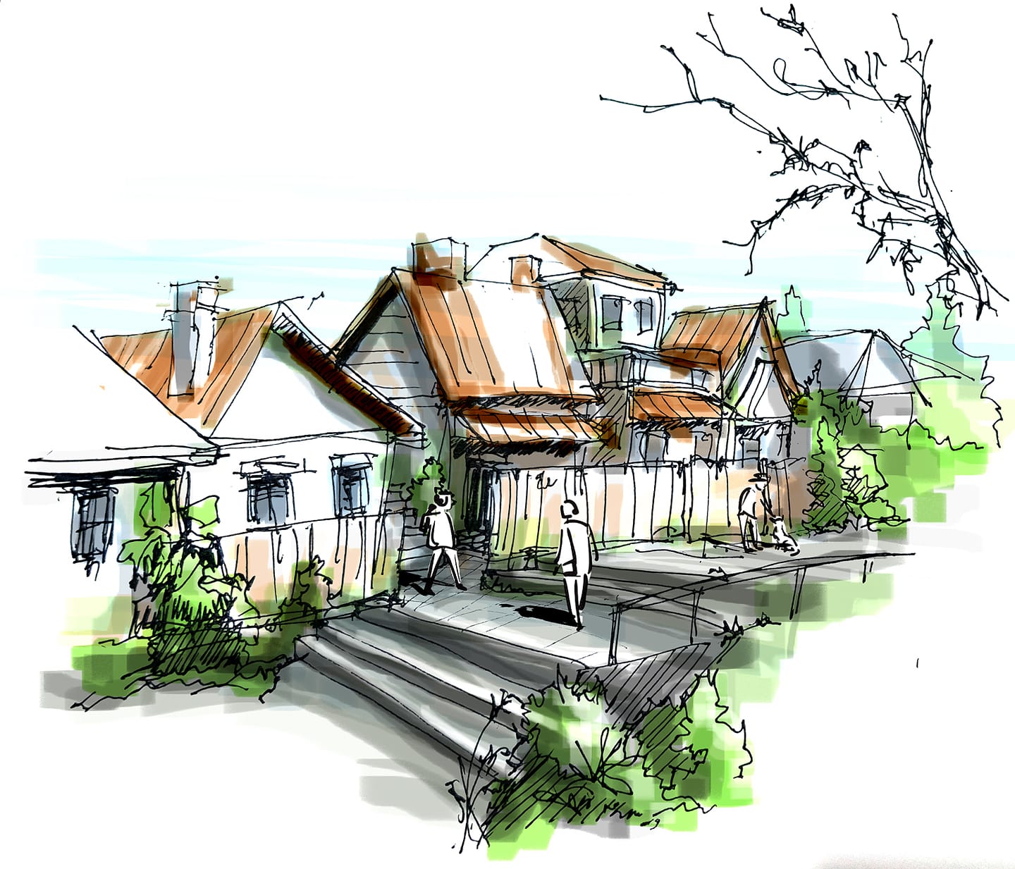
IMPRESSIONS : STREETS AND HOUSES (coloured)
-a sketch on old houses and streets, kampung style
-sketched in 120gsm paper using Uniball Signo.
-Colored in photoshop
-27 July2018
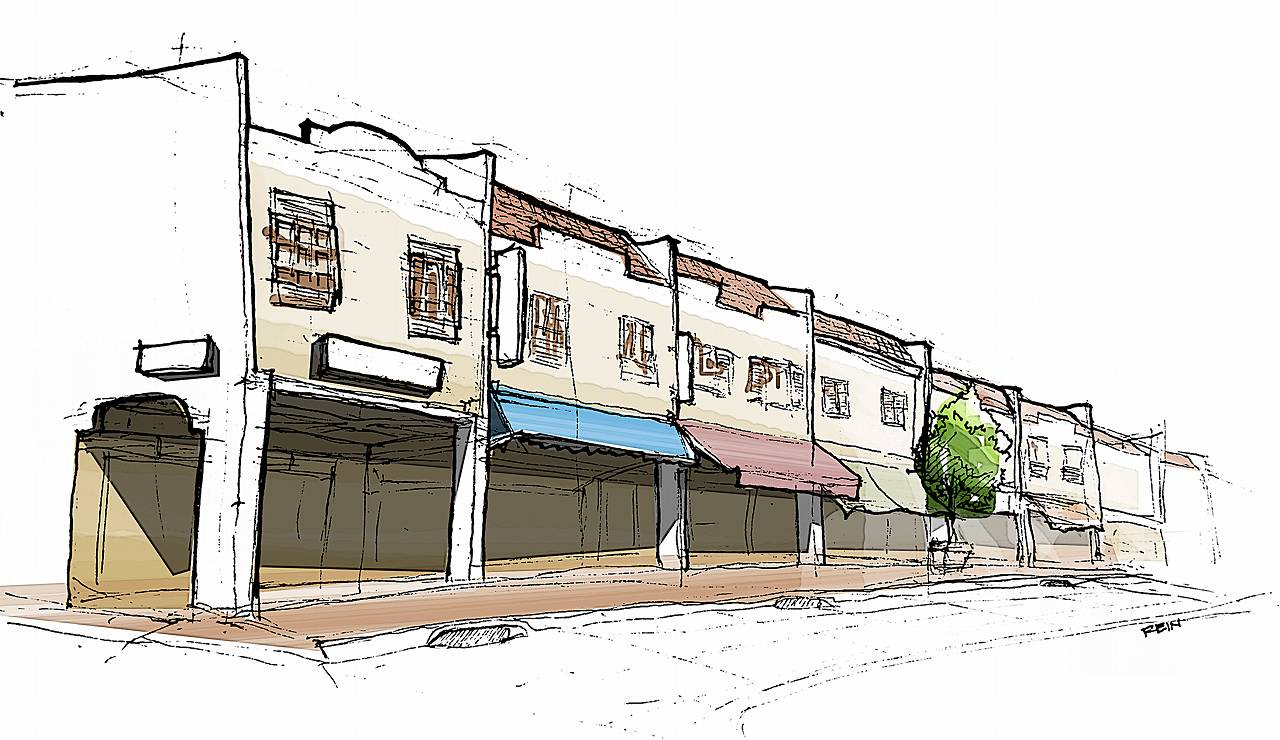
IMPRESSIONS : SHOP HOUSES (coloured)
-a sketch on how shop houses in singapore look like
-sketched in 120gsm paper using 0.2, 0.4 and 0.8 uni felt tip pens.
-Colored in photoshop
-17nov2015
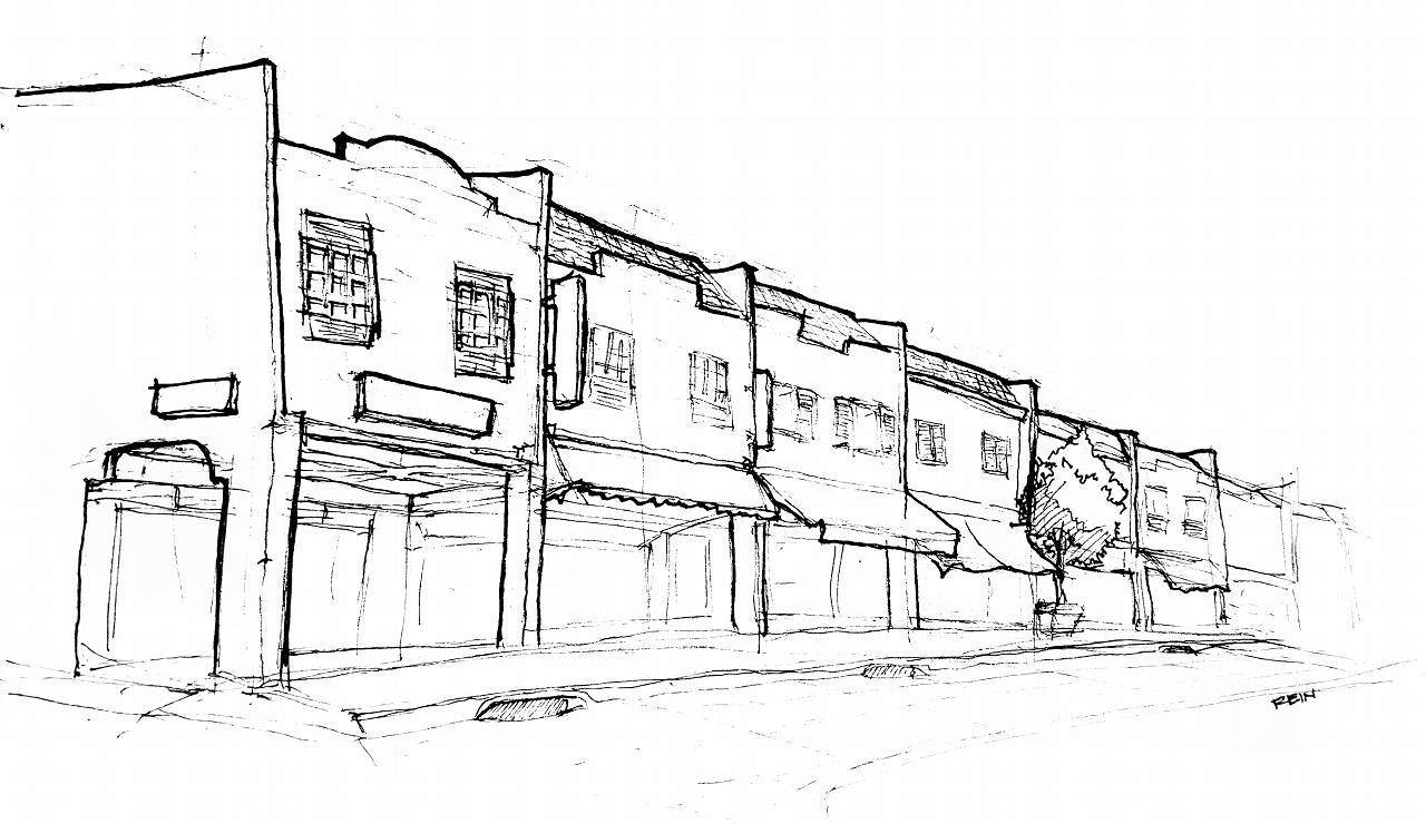
IMPRESSIONS : SHOP HOUSES
-a sketch on how shop houses in singapore look like
-sketched in 120gsm paper using 0.2, 0.4 and 0.8 uni felt tip pens.
-17nov2015
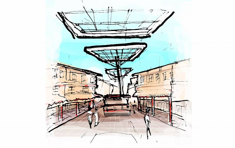
IMPRESSIONS : FOOD STREET AT CHINATOWN
-a very rough 10min sketch of chinatown food street.
-sketched in 120gsm paper using 0.2, 0.4 and 0.8 uni felt tip pens.
-colored in Photoshop
-16nov2015
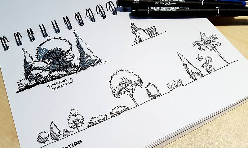
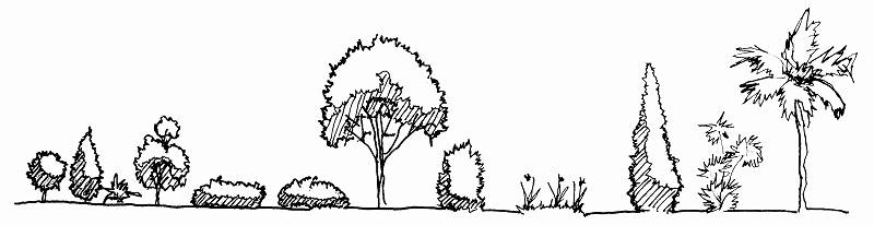
ENTOURAGE: TREES AND VEGETATION
-sketched in 120gsm paper using 0.2, 0.4 and 0.8 uni felt tip pens.
-15nov2015
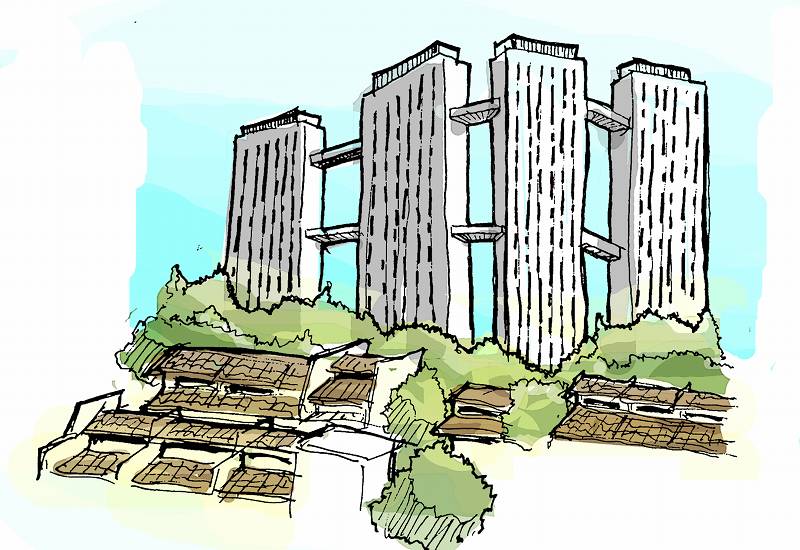
IMPRESSIONS : PINNACLE AT DUXTON
-this is an incomplete impression of the Pinnacle at duxton (4 of 8 towers).
-sketched in 120gsm paper using 0.2, 0.4 and 0.8 uni felt tip pens.
-colored in Photoshop
-14nov2015
CONCEPT : LIFE IN MONO
-sketched in 120gsm paper using 0.2, 0.4 and 0.8 uni felt tip pens.
-annotated and colored in Photoshop
-13nov2015

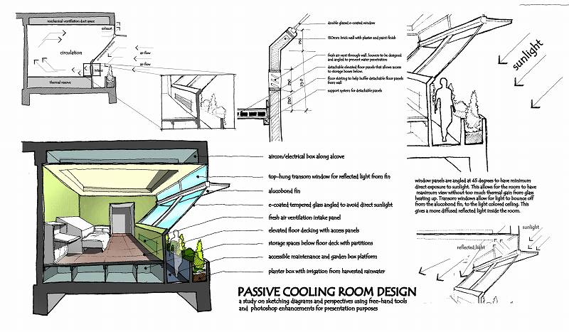
CONCEPT : PASSIVE COOLING ROOM WITH GARDEN
-sketched in 120gsm paper using 0.2, 0.4 and 0.8 uni felt tip pens.
-annotated and colored in Photoshop
-11nov2015


 OPTION 2
